Archive for the Category » Computers «

Saturday, May 22nd, 2010 | Author:

The last high performance DAC I built is almost old enough to vote.  so I thought I should try building a new one given the new direction my audio addiction is taking.  My old Tube DAC still sounds fantastic to this day; in fact I’m still using the same prototype board that I etched in an apartment while in graduate school.  However being tube based, not only is it a bit of a power hog, but I don’t like to leave it on for long periods of time if I’m not using it.

My current audio system goals are to have small unobtrusive little speakers and electronics driven by streaming audio from my laptop or my server.  These systems should be powered up most all the time, and be as high performance as I can make.  I am finding that as I get older, I rarely just sit and listen to music, so a dedicated listening room largely sits empty.  Maybe I need to turn in my audiophile card, and get a Bose mini system; except I still appreciate and demand good sounding, low distortion , high fidelity music.

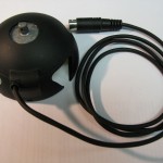
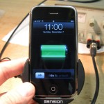
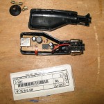
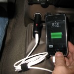
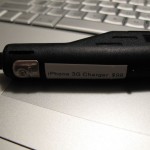
My current solution is to build high performance two-way speakers with high quality drivers, and drive them with digital switching amps which are very efficient and use very little power when idle.  The source for each of these little systems is an Apple Airport Express.  These little units let me stream my music as well as acting like little wireless routers and network extenders.  The sound quality from them is actually reasonably good, but it could be better.  They are welded shut during assembly, so there is no getting inside for some circuit improving, but in addition to analog output, they also output TOSLink optical digital signals as well.  This means that I can add a simple DAC between the Airport Express and one of my amps and improve my sound quality dramatically.

I had been toying with building a new DAC with Cirrus Logic chips (formerly Crystal Semiconductor) because the Crystal folks had consistently been making better and better sounding chips the last time I have checked into using them, and the Burr Brown offerings really dried up after Texas Instruments bought them.  I had played with asynchronous sample rate converters back in the AD1890 days, and they were a mixed bag sonically.  But I had read a great article at DIYAudio on how they work and why they can be very useful for digital audio.  Given that I am using a marginal TOSLink source, I thought that doing a bit of clean-up after the fact with one made some sense.  So I had picked out my chips:  CS8416 receiver, a CS8421 sample rate converter, and a CS4398 DAC.  After laboring over what to do with the needed analog stage, I got reading this enormous thread on a very inexpensive DAC on eBay.  If I had any brains, I would have just bought that DAC and called it good; well I did, but because I like to build things, I also made my own while I’ve been waiting for the DAC to arrive from China.

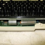
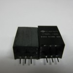
One of the major themes in that thread is using transformers as an analog stage for the DAC.  In general I find transformers to be nasty signal butchering devices, but maybe I’m getting more senile in my old age, but they appeal to me in that application.  The transformer is an ideal balanced to single ended converter, and the analog stage needs some filtering of ultrasonics, and the transformer does that as well.  For my application, I was also looking for something that would sound as good as my tube stage without the heat, power, and lifetime issues.  So I decided based on the glowing reports in the thread to give it a try.  But for good sound, just any old transformer won’t do.  I like the concept of circuit board mount transformers, and Lundahl has a great reputation for line level transformer sweetness.

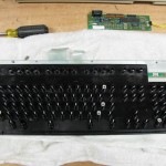
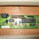
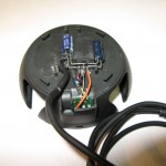
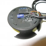
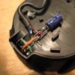
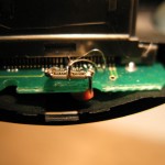
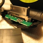
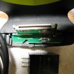
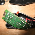
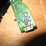
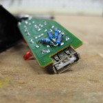
Shown below is my first prototype.  It uses a pair of the LL1690 amorphous core line level transformers being fed by a CS4398 DAC, which is being fed by a CS8421 sample rate converter.  The converter gets it’s data from a CS8416 receiver with both coaxial and TOSLink inputs.  An Airport Express pushes bits through the TOSlink to the DAC.  The DAC uses a PCB mount toroidial power transformer which feeds seven discrete power supplies for the three chips.

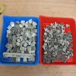
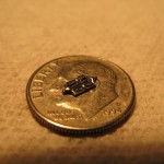
I laid out the board expecting to send it off to a professional board house if it was worthy, but I don’t have deep enough pockets to just buy pro-made boards for every hair-brained circuit I generate.  I etch those myself.  So I reduced my 4 layer board to a double sided board with poured ground plane regions.  I’ve never etched a board this fine (TSSOP and 0604 parts), but somehow I did it.  Then it was a matter of soldering and squinting.

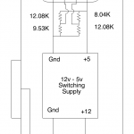
The schematic for the design is here:  DAC Schematic

The board layout is here:  DAC Board Layout

The parts list is here:  DAC Parts List

And now it’s time for some pictures:

Category: Audio, Macintosh  | Tags: , , , ,  | 5 Comments
Tuesday, March 16th, 2010 | Author:

I’ve been building speakers for myself and others as well as repairing Quad Electrostatic speakers for nearly twenty years.  A couple of my designs are shown on my website, as well as instructions and descriptions of how to repair the Quad ESLs.  One key tool needed in speaker design and repair is the ability to measure the speakers acoustical response.  I have used  Loudspeaker Lab to measure passive components, driver TS parameters, and speaker impulse response and sweeps.  Lately I’ve been using Fuzzmeasure on my Mac, which is a nice and simple package, and works well.  But nothing works exactly like you like to work except software you write yourself.  I have a complete passive component measuring, Driver TS parameter calculating, and speaker impulse and sweep response measuring suite written in LabView.  I’ll be posting a description of my software suite and lots of screenshots soon.

Regardless of the software used, a good microphone pre-amplifier is needed.  In 2002, I designed a measurement bridge loosely based on the Loudspeaker Lab box.  The controls were designed to match the Loudspeaker Lab box, and my measurement box contains a lot of the same functionality, but in a higher performance, more battery hungry version.  The measurement box contains a low noise wide bandwidth microphone pre-amp, an amplified impedance bridge, and an extra channel of buffering for amplifier compensation when measuring speakers.  In addition, I have a built in reference resistor (0.005%) to calibrate the impedance bridge.

This bridge allows me to measure and match crossover components (caps, resistors and inductors), measure driver Thiele-Small parameters (Delta Mass), and measure speakers; both impulse response (MLS based), and in-room sweeps.  I use this measurement box in conjunction with Panasonic WM-61A electret microphones.

Here is the schematic for my measurement bridge:

And here’s a few pictures of the measurement box itself.  It loves to eat 9V batteries:

Wednesday, December 31st, 2008 | Author:

Well after owning my Model M keyboard for nearly a decade, I decided that my key-cap cleaning and case wiping wasn’t enough. So I carefully removed the keyboard itself from the keyboard case and cleaned everything I could reach. This isn’t typically blog-worthy, but this is the legendary IBM Model M keyboard; the one true keyboard. So much has been written about this wonderful piece of engineering that I won’t elaborate. Wikipedia does a good job of it: Model M

I love my keyboard, and use it frequently. I do a lot of work on laptops these days and the Apple low profile aluminum keyboard is slowly winning me over with is sweet short throw sweetness. But the tactile feel and sound of typing on a Model M is a thing of beauty.

Sheldon

Monday, December 08th, 2008 | Author:

The original plan was to add a 5 volt regulator in the Dension cradle cable. I was planning to add it about 6 inches from the connector and heat shrink it when I was done like some sort of cable goiter. As I was checking out the back cavity of the cradle I realized that the regulator would damn near fit inside it. However, with the metal attachment bracket it wouldn’t quite fit. I ground down the metal bracket and sanded down the regulator a bit and everything fit perfectly. I added filter caps before and after the regulator to suppress noise and called it as day. The cradle is working well and is ready to install. As usual, pictures are below.

Monday, December 08th, 2008 | Author:

Last night I installed the voltage divider assembly into the Dension cradle.  I thought I had some fine soldering tools but my smallest Metcal iron tip looks like a Louisville Slugger next to the 30 pin cock connector pins.  It took some steady hands (which apparently I don’t have either), and some good diffuse light to make these connections.  I used a strand of silver plated copper wire to make the connections, and a piece of the full stranded wire to make the power connection to the voltage divider assembly.

It would have been a little less kludgy to make a new circuit board with the proper resistor divider traces on the board, but I’m not sure that I can make a boar with traces fine enough to reliably fit the connector.  I am also concerned that I couldn’t get the connector off the existing board without damaging it.  So this is the result.  It seems to work quite well at this point.

The next step is to step down the power coming into the cradle from 12(ish) volts to 5 volts.  A linear regulator doing this job would be dumping more power into heat than it provides to the iPhone for charging, which not only may overload the factory head unit, also requires the linear regulator be heat sunk somewhere.  V-Infinity has a really snazzy switching regulator that has an efficiency of about 92%. This means that during full charging, the regulator will only dissipate about 0.2 watts and will not need a heat sink.

Sheldon

Wednesday, December 03rd, 2008 | Author:

This resistor divider kludge marks the official start of modifying a pair of Dension Ice Link iPod cradles for use with 3G iPhones.  The Dension Ice Link is a cradle that fits a variety of Apple iPod models (and iPhones).  It plays audio out from the iPod through an OEM car stereo, and charges the iPod unless you have a 3rd gen nano, 2nd gen iTouch, or iPhone 3G.  These new models charge via USB only, and these old Ice Link systems only charge via FireWire.  With a little kludging, that problem is easily solved, and for $7 on ebay, these systems are a steal. 


Sheldon


Category: Audio, Automotive, iPhone  | Tags: , , , , ,  | Comments off
Sunday, November 23rd, 2008 | Author:

Several years ago I bought a Dension Ice Link to charge my iPod and play it through my Toyota stereo. This system has served me well though a 3rd generation iPod, a 5.5th generation iPod, and a 1st generation iPhone. A friend of mine went out and got himself a sweet 3G iPhone only to find out that many of the older accessories do not work with it. To date, there are no car cradle systems that both play the iPhone through the stereo and also charge the unit.

It appears that the newest generation of iPods (4th gen nano, 2nd gen touch, 3G iPhone) do not charge through the firewire pins of the dock connector anymore. They are USB only, and not just any USB either. So many USB chargers are blissfully ignored by the iPhone.

My friend’s desire to get a car integration system for his 3G iPhone and m desire to understand what had changed with the dock connector has led me to try to understand the changes in the newest generation charging circuit.

Information is pretty scant out on the interwebs, but I did find this: http://pinouts.ru/Devices/ipod_pinout.shtml
which talks about what appears to have changed in the charging circuit, and why any old USB charger won’t charge a 3G iPhone. Cutting to the chase, the issue is that the USB dock pins are in fact used for charging, but having 5 volts present on the 5 volt pin of the USB plug of the sync isn’t enough (and ground obviously). The Data+ and Data- lines need to be held at a certain voltage for the phone to recognize that it should charge.  The Data+ pin needs to be held at 2.8 volts, the Data- pin needs to be held at 2.0 volts.

I have a craptastic generic USB car charger that would not charge my first generation iPhone.  This charger like every generic USB charger I’ve measured leaves the data pins floating.  This strikes me as a very wise decision, but makes it a non-starter to charge the iPhones.  I cracked my generic charger open and added a pair of voltage dividers form the 5volt pin to the ground pin.  I chose resistor values I had laying around to produce the 2.0 and 2.8 volts.  The pinouts.ru link suggested different values for the divider resistors, the absolute choice seems to not be critical.  Shown blow is some pictures of the process.  

This is the first step in modifying my Dension Ice Link for charging 3G iPhones.  My friend bought an Ice Link from ebay for $30 and we are going to mod the cradle for charging 3G iPhones.  Stay tuned for that later.  

Category: Audio, Computers, iPhone, Tacoma  | Tags: , , , ,  | 4 Comments