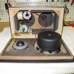
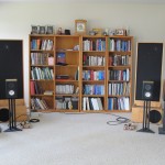
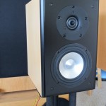
The Jordan JX-92 is a great little driver, but has some raggedness in the upper frequencies. Below about 4KHz, the driver has a clarity and an uncolored response that is very impressive. The bass response, while not window-rattling, is really impressive for a 5.5″ driver. To take the good stuff from the Jordan and not get the bad, I decided to mate it up with a tweeter. But not any old dome tweeter would do the Jordan justice. I considered a ribbon, but I kept coming back to the Vifa XT-25 as a great mate for the Jordan. The crossover point is nice and high, so the XT-25 won’t be stressed. The character of the XT-25 also matches the Jordan driver quite nicely. Finally, the deciding factor: I had a pair of them.
The beginning of this project can be seen here: http://getinthewoodchipper.com/?p=181 Where there are pictures of the cabinets being routed, and the drivers mounted.
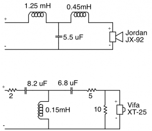
The jordan is designed to not roll off in the treble, and the Vifa XT-25 doesn’t seem to know it’s tweeter. So in order to get a reasonable crossover rate and not have a huge upper midrange muddying region where both drivers are contributing, the drivers need to be crossed over pretty hard. After messing with 2nd order crossovers, it was pretty obvious that it wasn’t rolling the drivers off fast enough. 4th order filters worked pretty well, but the parts count was crazy, and the sound seemed somewhat pinched off and odd sounding in the crossover region. I settled on a 3rd order crossover (electrical) for both the woofer and tweeter. The woofer crossover is a butterworth topology, and the tweeter circuit is somewhat of an unknown that compliments the response of the woofer.
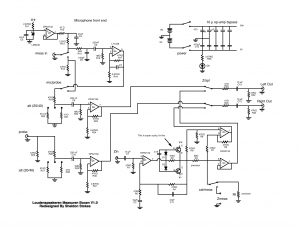
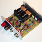
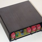
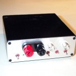
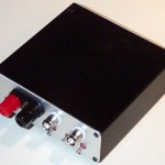
I used my computer and an external USB soundcard with my impedance bridge and microphone pre-amplifier, a Panasonic WM-61A electret microphone capsule, and my modified Dyna SCA-35 to drive the speaker as the basis of the measurement hardware to design the crossover. I used two different software suites to do the driver response measurement.
I used Fuzzmeasure, which uses a swept-sine deconvolution to calculate the impulse response. I also used software of my own design which uses MLS sequences to calculate the driver impulse response. Fuzzmeasure is a very slick and easy to use program, but it seems to show a rosy picture of the response. The drivers are in no way as flat as it makes them out to be, but the crossover region seems to be represented accurately. Small changes in the crossover show up in the response. Update: I was over-driving my Fuzzmeasure measurements and that causes the flat-top readings shown below. My program is also slick and works the way I want it to, and I have control and understanding of the processing the program does. My code also matches the impulse response of Loudspeaker Lab.
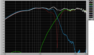
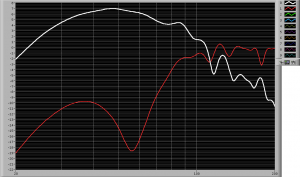
Here is the speaker response as measured with my software. Note that my impulse response is “windowed ” to eliminate the room response. But the windowing process also rolls off the bass response, so anything below about 300Hz is artificially rolled off on the plots below. The first plot is the impulse response, woofer and tweeter response, and the null from the tweeter polarity reversal. The second plot shows the port contribution and woofer null with close microphone placement at the driver cone and port exit. The red woofer trace shows the current port tuning at about 55Hz. The Jordan is still breaking in, and I’ll lengthen the port to tune it to about 45Hz when the Fs of the Jordan drops.
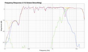
The output of Fuzzmeasure is shown below. Note the insane smoothness of the Jordan driver (compare this to every other measurement you’ve ever seen of the Jordan). But the crossover information looks very similar. Update: The smoothness is due to over-driving my input signal, which was not obvious to me. I’ve since fixed my problem and the Fuzzmeasure readings and my software readings agree very well. Fuzzmeasure is a great Macintosh program for speaker and audio measurements.
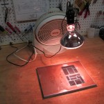
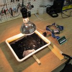
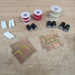
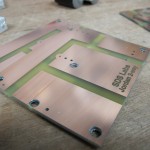
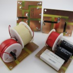
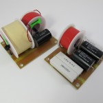
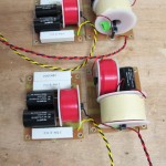
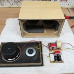
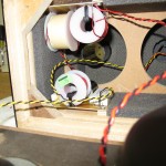
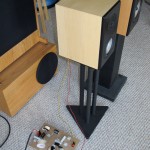
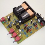
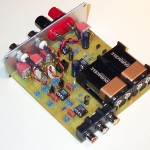
Here’s some pictures of the crossover build-up process:
PCB Layout File: jordan2way_crossoverPCB

