Author Archive

Monday, November 06th, 2017 | Author:

The Quad ESL-63 has gone through several revisions of the input protection boards.  The latest design uses a bridge rectifier and zener diode stack similar to the treble panel protection circuit in the Original ESL’s.  This is combined with a simplified arc detection and clamp circuit.  This latest design has been used in all the subsequent Quad ESL models from the 988, 2805, and 2812 models.  

The arcing clamp circuit senses the electrical field from an arc with a short antenna by rectifying the signal with a diode.  This rectified signal turns on a transistor which clamps the input on a 555 timer chip wired as a one-shot.  This then turns on a TRIAC which shorts the input to the speaker.  

The OEM arc clamp board also contains the input ballast resistors as well as a capacitor “zobel” for the input transformers.  In the OEM circuit the input series resistor (1.5ohms) and parallel capacitor (220uf) are mounted to the chassis.  

I have designed a replacement zener clamp board which is much like the OEM unit, but uses surface mount zener diodes.  I have also designed a replacement arc clamp board which uses precision ballast resistors and also incorporates the input resistor and parallel electrolytic capacitor.  And a needed improvement is provisions for adding a healthy sized film bypass capacitor across the input electrolytic.  

The schematics and layouts of both boards are here:

ESL-63 Arc Clamp Board Schematic

ESL-63 Zener Clamp Board Schematic

ESL-63 Arc Clamp Board Layout

ESL-63 Zener Clamp Board Layout


Category: Audio  | Tags: , , ,  | Comments off
Monday, November 06th, 2017 | Author:

For a number of years, I suggested a gas discharge tube to protect the original Quad ESL treble panels.  and they do work well, but I’ve had them get leaky over time and their striking voltage drops.  I have reverted to the stock Quad ESL treble protection circuit.  The original circuit is a rectifier bridge of 3000 volt diodes, where the input to the treble panel is applied across the AC inputs of the bridge.  A stack of zener diodes is placed across the rectified outputs.  

I’ve designed a little board to fit under the input transformer case.  The schematic and layout are shown here:

Clampboard Schematic

Clampboard Layout


Category: Audio  | Tags: , , , ,  | Comments off
Monday, August 28th, 2017 | Author:

The vast majority of the original Quad ESL’s have rectifier modules that consist of a bakelite box with a circuit board sticking out the top and filled with bee’s wax.  This module can reasonably be rebuilt by heating the blocks in an oven (at 275F) to melt the wax out, and then replacing the components on the circuit board.  When complete, the molten wax is then poured back in the box with the circuit board and allowed to cool.

However, the early Quad ESL’s came with epoxy potted blocks that are not rebuildable.  And occasionally I’ve come across speakers which are not complete, and the rectifiers are missing.  I designed a replacement rectifier block as an upgrade to the original design.

My design uses the same cockroft-walton voltage multiplier as the originals, but rather than running the panels straight off the multiplier, I isolate the panels through a series resistor and a neon bulb (like the Quad ESL-63 circuit).

SDS Labs Quad ESL EHT Schematic

IMG_1352

IMG_1355

IMG_1353

Category: Audio  | Tags: , , ,  | Comments off
Thursday, May 02nd, 2013 | Author:

IMG_2394

The Citation II that I have been posting about originally had no power switch.  It was customary at the time that the pre-amp would switch on the power amp.  In the past, I’ve shaved down a small rocker switch to fit into the courtesy outlet.  This worked well, but I’ve always been concerned about the amount of material I had to remove from the sides of the switch to make it fit in the courtesy outlet.  It was certainly a fire waiting to happen.

Jim McShane let me know that a C&K slide switch fits in that spot perfectly.  And so it does, but the C&K slide switch I bought was all plasticy and generally crappy, I’d suggest a better version.  Rather than hunt for a new and better slide switch, I decided to put a beefy toggle switch in the courtesy outlet.  But I have a general rule that I never cut metal in my mods.

So I built a FR4 fiberglass structure to hold the switch, which seems to be the motif for my mods on this amplifier. The structure consists of three layers of 1/16″ thick boards.  The back most layer has a small hole that the switch attaches onto.  The next two layers are spacers to keep the front locknut away from the inside of the chassis so the switch will sit flat.

The results are shown in the pictures below, notice the inrush current limiter, which is a very good idea and allows you to lower the fuse to 5 amps.

IMG_2396 IMG_2397 IMG_2402 IMG_2403

Category: Audio  | Tags: , , ,  | Comments off
Sunday, April 28th, 2013 | Author:

IMG_2305

The Citation II is certainly a lovely amplifier, and has been a workhorse for me over the years.  I’ve owned four of them to date.  With every one of these that I have rebuilt, I’ve modified the bias meter circuit.  The Citation II bias meter has two marks on it, an AC balance mark; which is the neutral needle position with no current input to the meter.  The second mark is a “bias mark” which is the desired operating point for the tubes and is adjusted with four bias potentiometers.  The two mark meter makes setting AC balance and DC bias un-ambiguous, but it doesn’t lead to any flexibility when using many modern tubes which require less plate power dissipation.

The DC bias portion of the meter circuit uses 15 ohm resistors inserted between each output tube’s cathode and ground.  This “sense” resistor arrangement produces a voltage at the tube cathode that is proportional to the current through the tube via Ohm’s law (V =I * R).  The meter circuit uses that voltage to move the needle.

The meter itself is really an ammeter, in that the needle displacement is proportional to the current flowing through the meter coil.  The coil resistance is really quite small.  The current required to move the needle to the center of the bias mark in my meter is 3.77 mA.  The meter circuit uses a series resistor to set the voltage versus needle position relationship.  for example, if I wanted 1 volt across the meter to move the needle to the bias mark, I’d put a 265 ohm resistor in series with it.

The very early Citation II’s (which the Sam’s PhotoFacts seem to be based) had a 470 ohm resistor across the meter, so if the original (outside the chassis) meter had the same sensitivity, that would be a voltage of 1.77 volts.  For the 15 ohm cathode resistors, that means that each output tube would have been drawing 118 mA for a plate dissipation (assuming a 460 volt B+) of 54 watts.  I suspect that the original meter was less sensitive, but I have no way of knowing, as I’ve never owned a very early citation.  The later internal meter units had 330 ohm resies resistors installed for a plate dissipation of 38 watts per tube.  However, in an addendum to the assembly manual, HK suggests that the 330 ohm resistor be reduced to a 300 ohm one.  This reduces the quiescent plate dissipation to 34.7 watts per tube.  However this is still very close to the maximum allowable plate dissipation of many modern 6550 or KT88 tubes; for example the Svetlana 6550C has a max plate dissipation of 35 watts.

So in the past I’ve always changed that resistor to a smaller value to run 30-32 watts on the plates of the output tubes.  Other references out on the web suggest changing the cathode resistors on the output tubes rather than change the series resistor in the meter circuit.  Either will accomplish the same goal, but changing the cathode resistors requires changing four resistors instead of one, and they are much more difficult to get to.  The output tube cathode resistors are buried between the power supply bracket and the input tag-boards.

IMG_2362

The goal of the circuit shown above is to provide several settings for the bias meter that will not require soldering if the output tube brand or type is changed.  The circuit uses a set of three resistors that are switched in and out of the circuit with a rotary octal switch and a fourth resistor in series.   These resistors provide seven combinations of overall resistance that allow the meter bias point to be set to 6 usable positions from the stock (330 ohm) value down to 30 watts of plate dissipation.

Citation2MeterChart

Position 2 is the stock value, and position 3 is very close to the value specified in the addendum.  Positions 4-7 allow a range of values to be selected for modern KT88 class tubes.

The board is held in place using the meter retention bolts and 1/4″ square section aluminum stock which has been tapped at one end and cross-drilled and tapped at the other (both tapped 6-32).  This provides a secure mechanical mount for the meter adjustment circuit, etched onto a small circuit board.  The layout and a simple schematic for this boar is show here:  meterAdjustBoard

Changing of the meter range is as easy as flipping the amp over, removing the bottom cover, and turning the knob to the desired position.  The table shown above was taped to the chassis to assist in setting the proper meter range.  The advantage to having the circuit inside the amplifier is that no metalwork has been modified, and the amplifier can be returned to the stock configuration at any time.


Citation2MeterModGraph

IMG_2387 IMG_2388

Sunday, April 28th, 2013 | Author:

The Harman Kardon Citation II is a great amplifier to be sure, but there are some limitations to the design.  One of the problems that has bothered me over the years are the terminal strips and the poor quality input jacks in the original design.  Many years ago I solved the input jack problem with new FR4 input boards that hold modern high-quality RCA jacks.

IMG_3886

IMG_3885

As seen in the photo’s above, a set of three layers of 1/16″ thick FR4 fiberglass was used to provide a platform to mount modern RCA jacks.  the four holes at the corners of the boards mate perfectly with the mounting holes in the Citation II chassis.  The bottom layer has smaller holes designed to accept the RCA jack and nut.  The next two layers act to space the mounting nut away from the amplifier chassis to prevent the RCA return connection from being shorted to the chassis.  This simple change allows high quality connections to the amplifier without modifying the metalwork of the amplifier at all.

IMG_2347IMG_2363


The second modification is aimed at making the speaker connections more reliable and easier to use with a variety of modern speaker cables.  The original amplifier terminal strip provides four connections for each speaker, a ground return and three different taps on the output transformer for three different nominal speaker impedances (4, 8, and 16 ohms).  The chassis cutout for this terminal strip is fairly small and would at most provide room for three connections.  My solution is to move the terminal strip inside the amplifier chassis and provide a pair of modern 5-way binding posts.  This was accomplished with a set of FR4 fiberglass spacers, much like the RCA jack spacers.  This time two layers of 1/16″ fiberglass was used.  The back layer is the same size as the original terminal strip and mounts tot he chassis using the same mounting points  The front layer acts purely as a spacer to account for the chassis thickness and allows the 5-way binding post bases to sit flush on the spacer rather than straddle the cutout in the chassis.

The set of spacers is held to the chassis by a bolt from the outside, and rather than a nut on the inside, a threaded bar is used.  This bar is made of 1/4″ square section aluminum bar stock, which is drilled and tapped (6-32) on one end and drilled and tap in the side at the opposite end as seen in the picture above.  This allows the bar to act as a nut to hold the 5-way binding post plates on the chassis and also provides a secure mounting point for the terminal strip inside the chassis as seen in the photo above.

The tweeter-saver components as mounted to the back of the terminal strip as they were in the stock amp, and the feedback and ground reference wires are attached to the back of the terminal strips as well.  However, the ground reference lead does not go tot he chassis as it did in the stock form; now it runs back to a common power supply ground.

A set of short leads with spade lugs on the end of them attaches the 5-way binding posts to the original terminal strips inside the amplifier.  The means that to change speaker taps, the amplifier has to be inverted and the 5-way binding post wire moved to the appropriate lug on the terminal strip.  However, in return for the inconvenience, the amplifier speaker connections are more robust and useful with many modern speaker cables.  And the chassis metalwork is never touched.

IMG_2378

IMG_2375

Tuesday, April 16th, 2013 | Author:

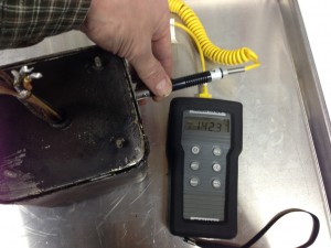
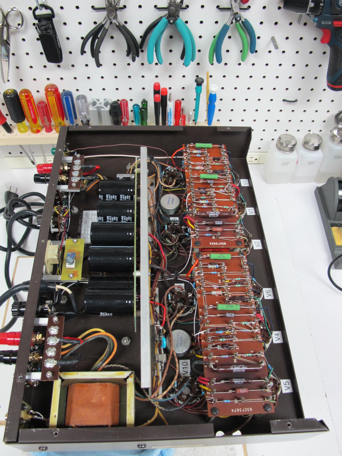
I bought a Harman Kardon Citation II Tube amplifier (my forth I’ve owned over my lifetime) from eBay. As is common, the previous owner chose not to, or didn’t know, the condition of the amplifier when he sold it.  I took a risk and bought it, as it looked to be in nice shape and I was taken in by the included tube cage.  Upon receiving it, I opened the bottom and measured the transformers.  One screen grid lead had high and inconsistent readings.  At first it was 20 kOhms, then it tropped to 4 kOhms, then down to about 50 Ohms, and back up.  Wiggling the wires coming out of the transformer didn’t change the reading at all.  I knew the worst, there was a fault somewhere inside the metal can, which is filled with tar.

IMG_2320

I really had nothing to lose, so I decided to get out the torch and see what was inside the can. I didn’t think I could actually fix the transformer, but not trying is admitting defeat.

The trick is figuring out how to get into the potted case to the transformer itself.  The top and sides of the can are drawn and are a single unit.  The bottom is a second piece and I suspected was stamped so that it had short sides that nested inside the body of the can.  The seam is then soldered.

It was unclear if the mounting studs for the transformer can also passed through the transformer laminations.  If the mounting studs also held the transformer, then the top of the can would slide off the transformer, if not, then the bottom would come off by itself.  I scritched and scratched around the mounting studs with a scribe to try to find a gap which would indicate that the bottom plate is slipped over the studs late in manufacturing.  I didn’t find any such gap, so I assumed that the studs were press fit into the bottom cover.

IMG_2344

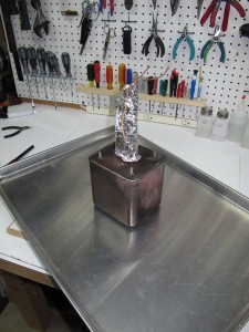
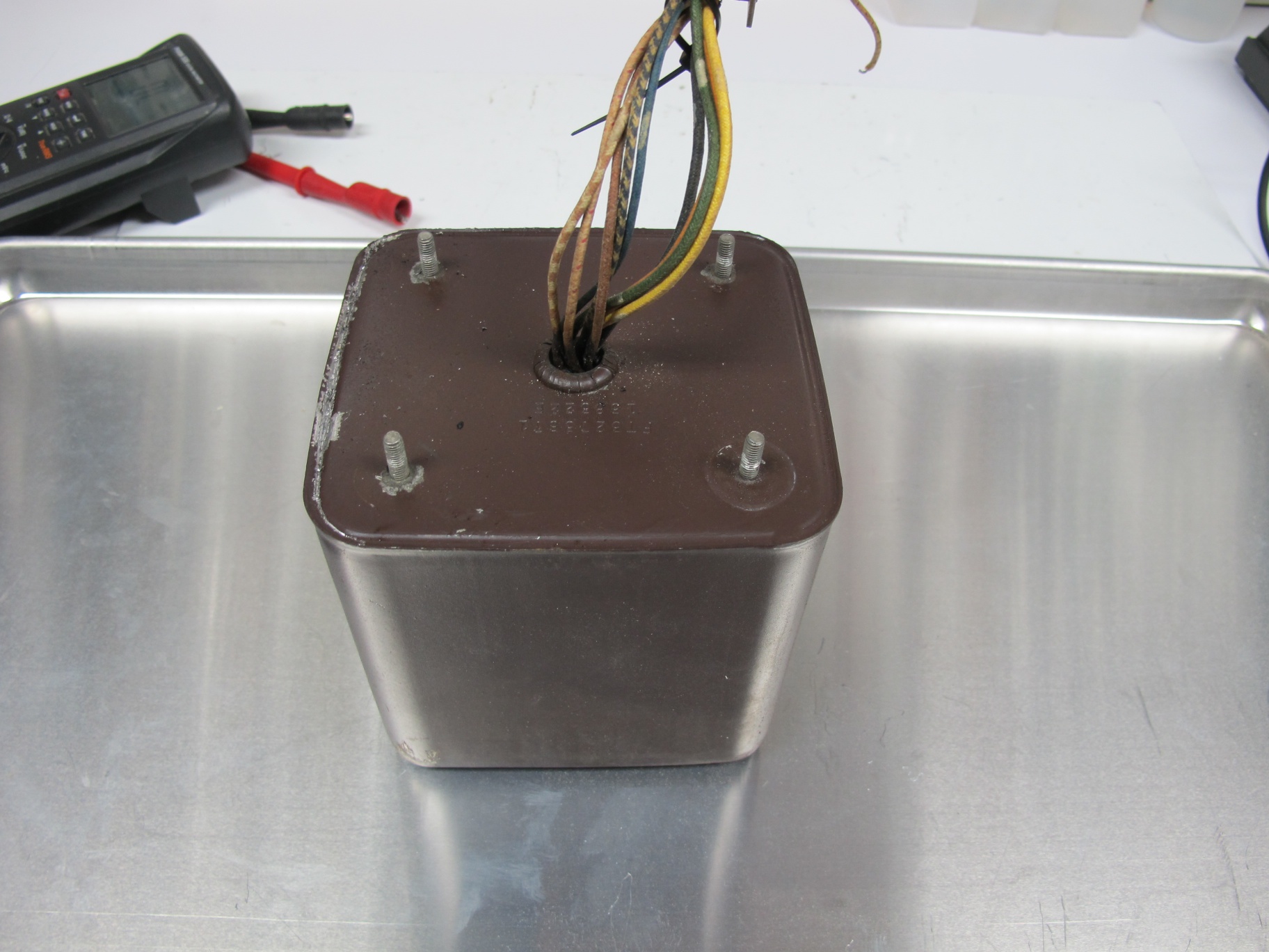
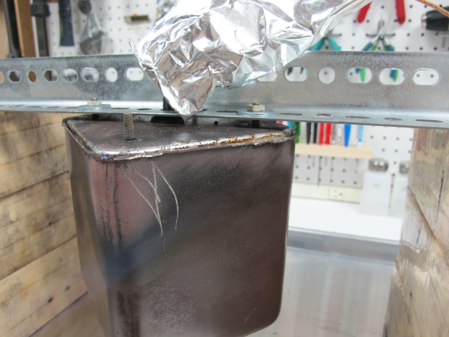
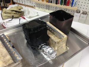
The first step is to suck out as much solder as I could.  I took a small oxy-propane torch and a vacuum pump as well as a solder catch can.  The catch can is a glass bottle with a plastic lid.  I drilled two holes in the plastic lid for two pieces of aquarium tubing.  One of the pieces of tubing is hooked to the vacuum pump, and the other piece of tubing is attached to a piece of stainless tubing.  The torch is used to locally soften the solder and with my other hand, I would suck it out of the crack with the tubing.  The transformer has so much thermal mass, that without a huge torch, there’s no hope of melting the solder all the way around.  If I could have added that much heat, I would be risking the transformer insulation.  So I relied on localized heating.  The photo to the left shows the transformer with the solder sucked out as best as I could.  The aluminum foil is actually two layers of foil with a damp paper towel sandwiched between them.  This prevents the leads being damaged if I am not careful with the flame.

IMG_3897IMG_2324

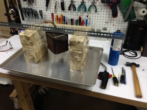
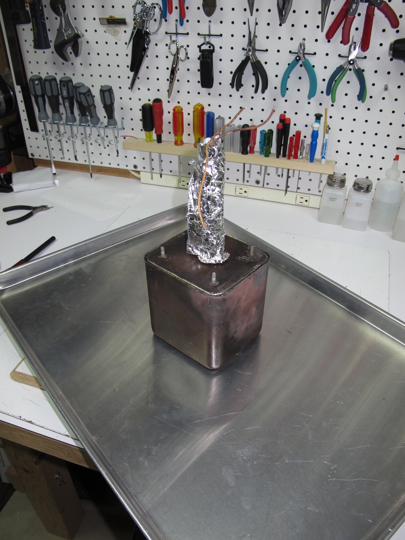
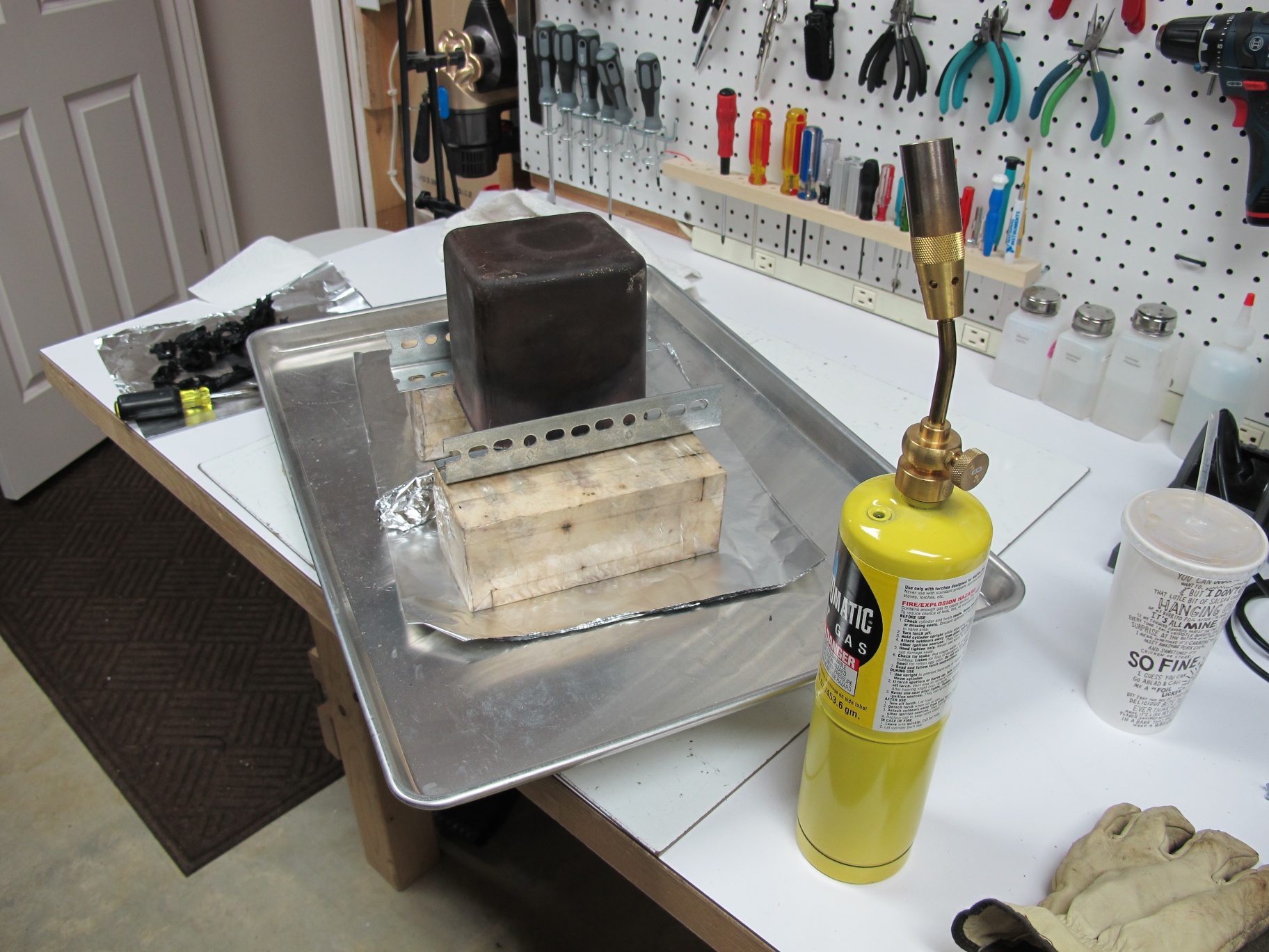
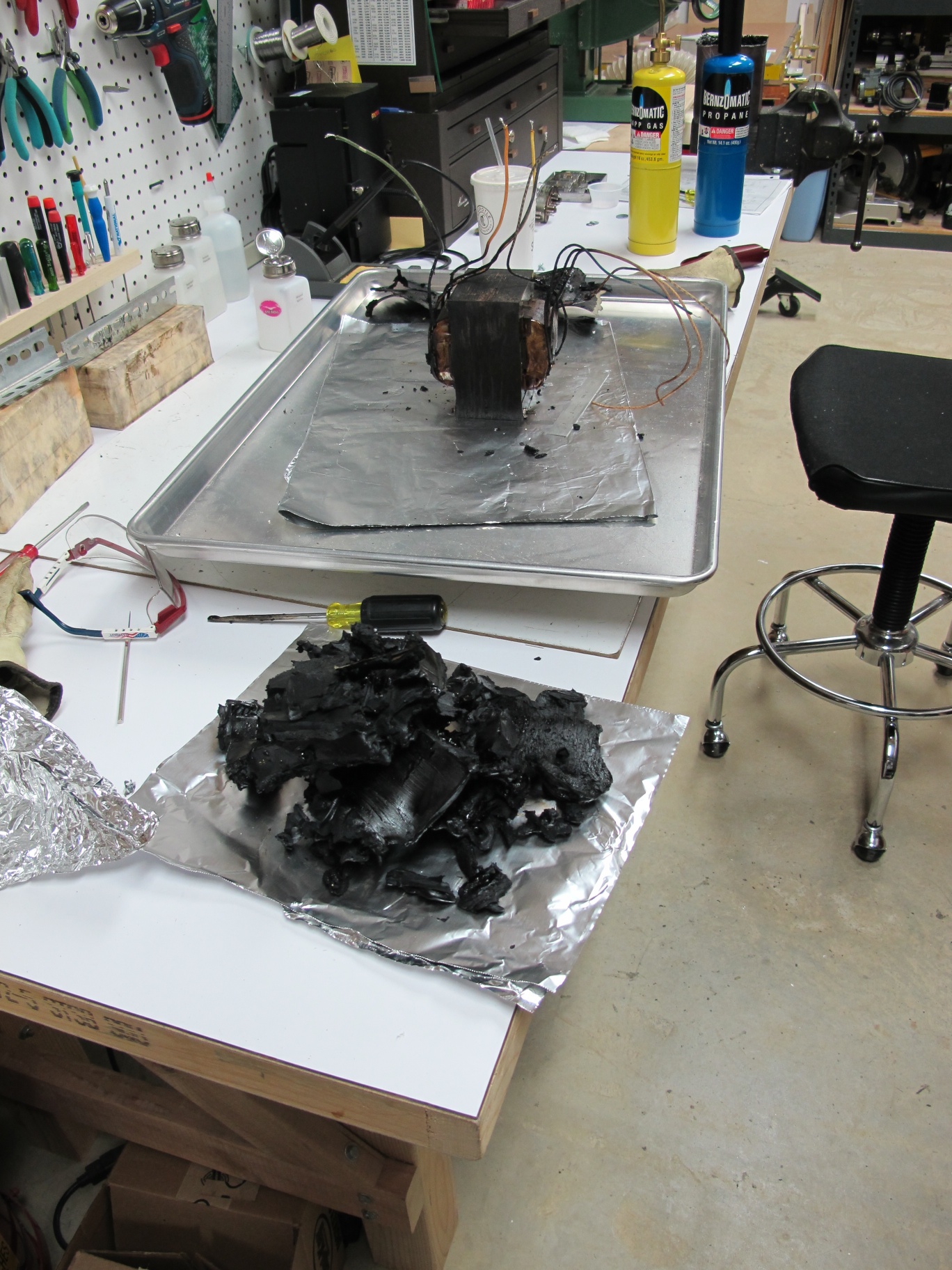
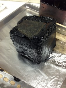
Shown above is the transformer with the solder removed and I’m in the process of trying to soften the remaining solder so the lid comes off.  I’ve switched from the very hot and localized oxy-propane torch to a simple propane torch, which has a much larger and cooler flame.  I was hoping that the larger flame would allow more even heating of the seam area and would free the lid.  I did some hammering on the seam as well, which I shouldn’t have, but I wasn’t sure if it was press fit or not.  It turns out that the solder seam was deeper and more extensive that I had guessed.

IMG_3899


IMG_2329


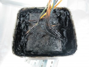
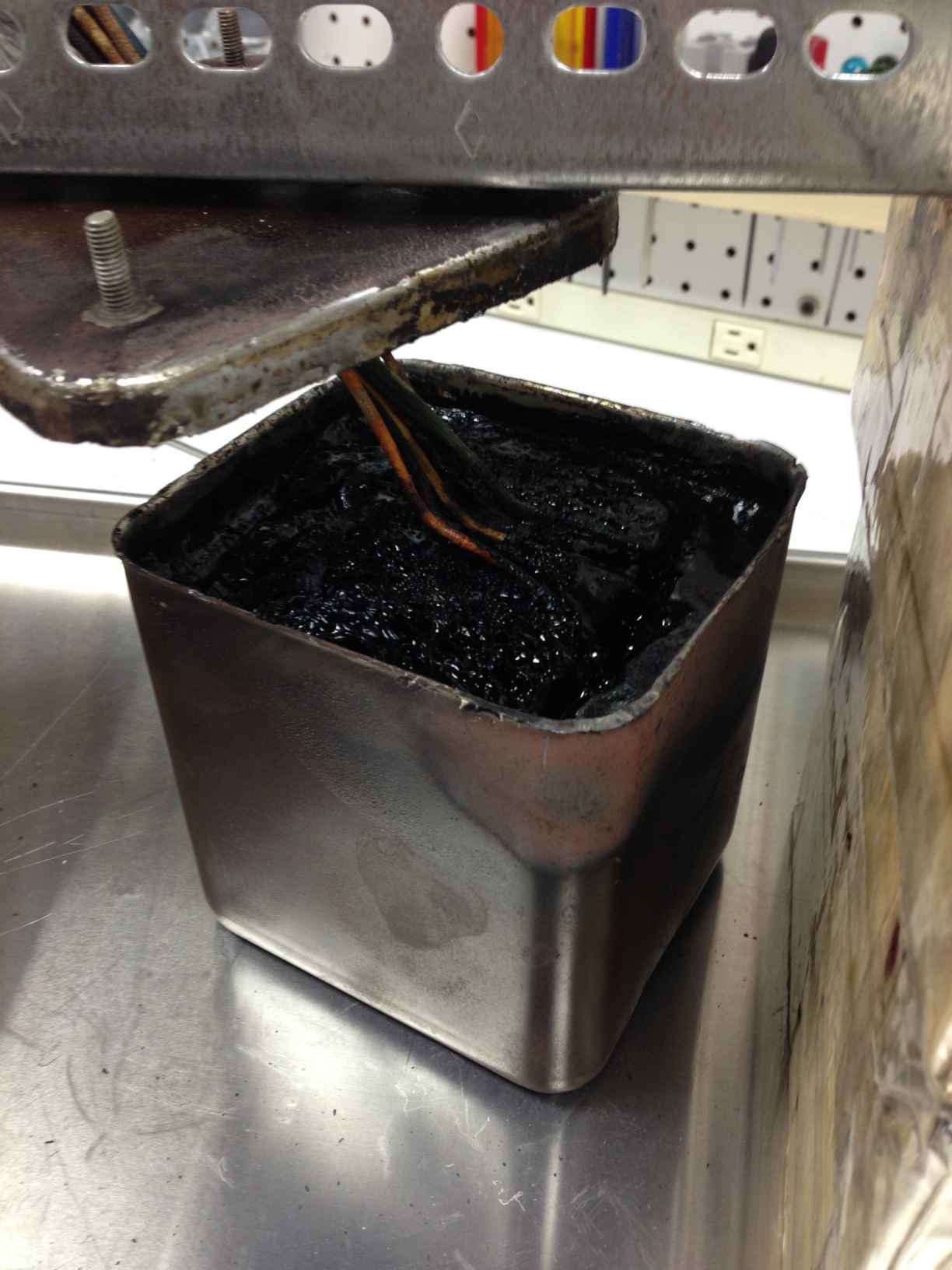
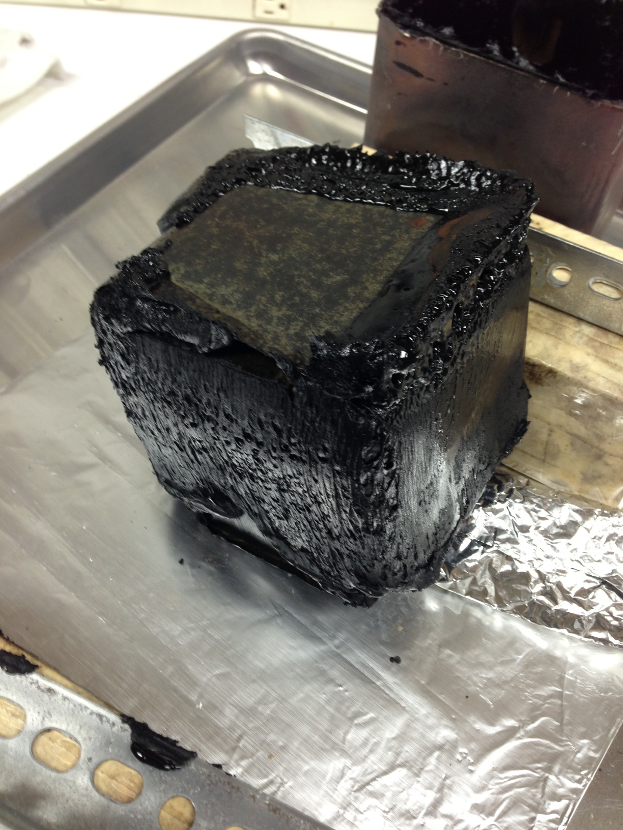
After a lot of heating around the seam area, the transformer can dropped onto the tray with a big thump.  My worst fears were realized, it was full of tar, and it smelled awful.  With the lid off, I could see that I had more work to do, because the transformer was still stuck in the can under all that tar.

IMG_2331IMG_2332

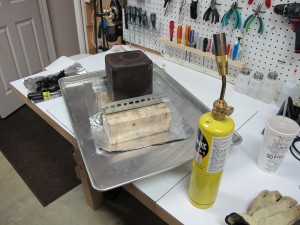
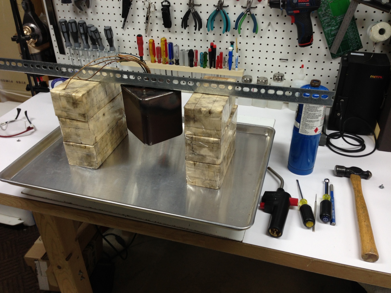
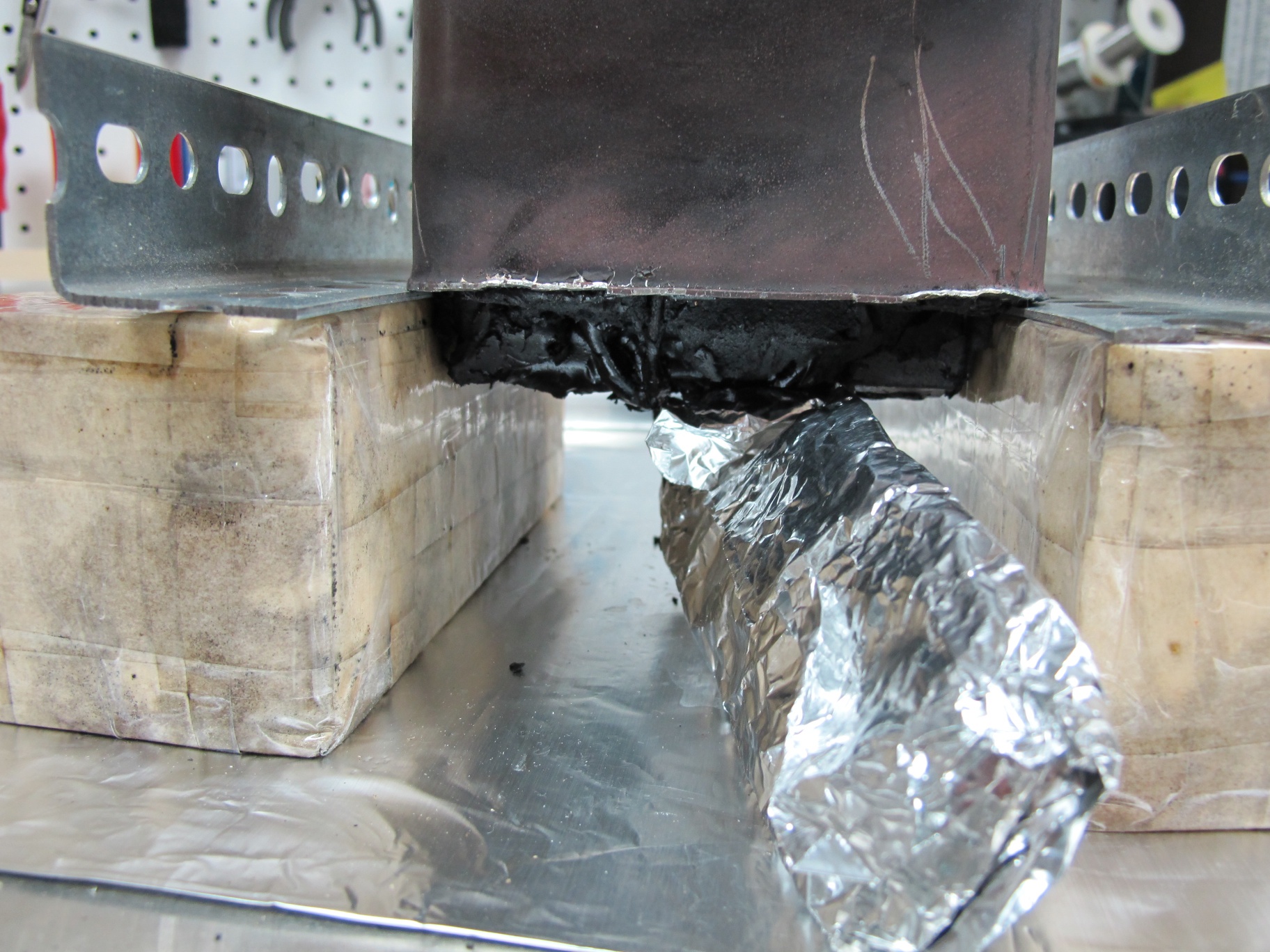
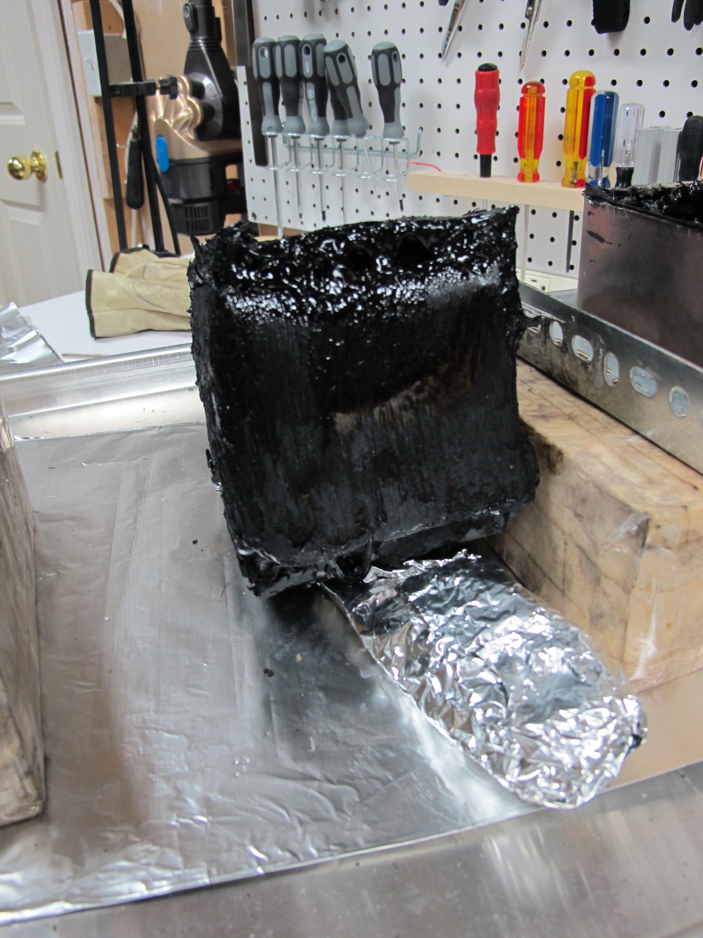
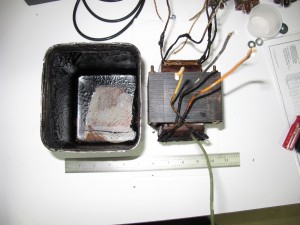
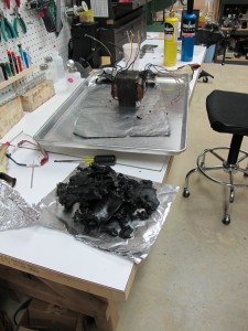
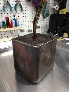
I flipped the transformer over and supported it on the edges of the can using some angle iron.  The tar wasn’t coming out at all because the tar at the top (bottom) of the can wasn’t hot enough to be liquid.  So I pulled out a third torch, which is a big mapp gas unit with a very broad rosebud type of flame that is ideal for gently heating a large area.  As I heated, the guts of the can slowly slid out onto the tray.


IMG_3900IMG_3901IMG_2335


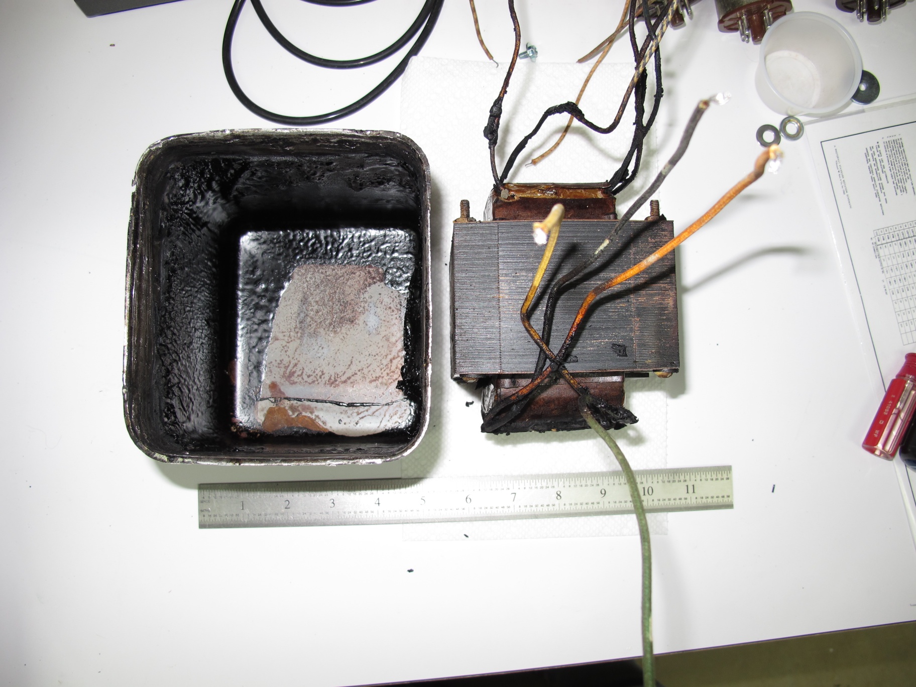
The potting tar doesn’t completely fill the can.  The top of the can had no potting compound at all, as apparently most do not.  If you tap on the top of a mounted transformer it sounds hollow, an indication that there is no tar on that face.  The transformer has a band of insulating paper around it along the long two axes.  However, the tar has permeated in around the paper.

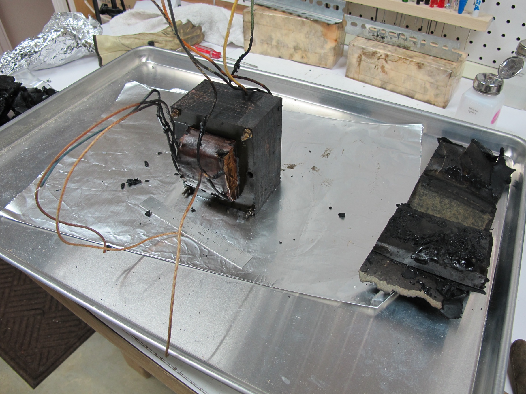
Fortunately, the tar has a nice property, if it’s cold, it’s hard as a rock (too hard to be a good potting compound), and if it’s really hot, it’s a liquid.  But in between those temperatures, it’s a soft putty consistency.  The process of softening the tar up enough to slide out of the can, left the bulk of the tar in that nice plastic state.  It was easy to peel it away from the transformer and it left the transformer really quite clean.

IMG_2343

IMG_2337

IMG_2338

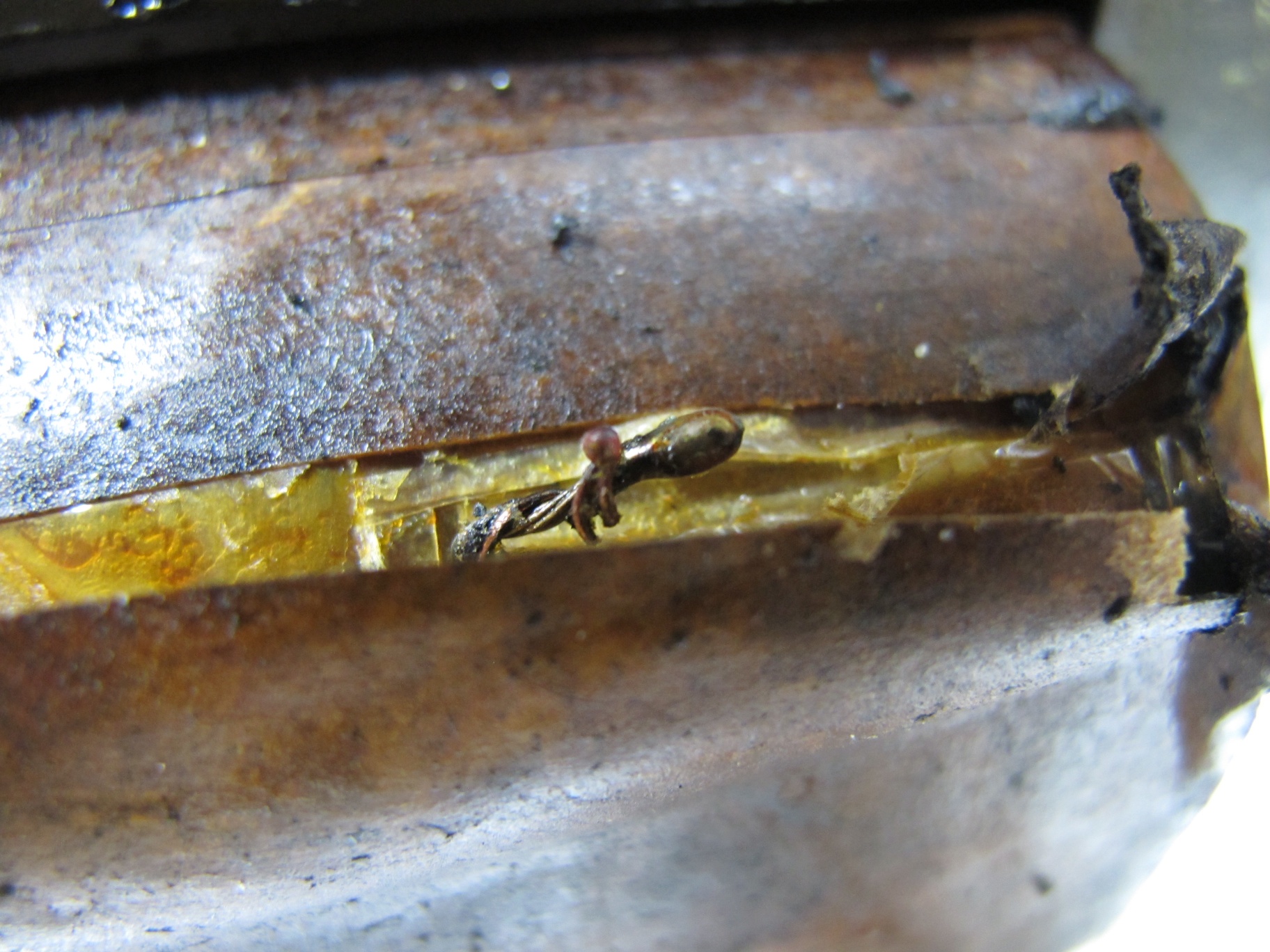
Now it was the moment of truth, time to find the fault.  I attached my multimeter to the primary center tap and the offended screen grid lead.  The resistance was now about 25 kOhms, a new value.  I poked the insulating wrap where the screen grid lead goes in, and bam, open circuit.  I poked some more and got another high resistance reading.  That was really good news, as the fault was right at the surface.  The figure below shows the fault exposed.

IMG_2341

The fault is the transformer copper wire melted away from the stranded wire lead that exits the transformer body.  I suspect this is a common fault point because there is a natural air pocket there.  The bulk of the windings have a lot of contact area with the neighboring windings and also to the insulating material on either side.  But the exit point doesn’t have that luxury for heat transfer, and apparently it overheated and melted back from the contact point.  Something serious happened to the screen grid of that output tube.  There was some melt products that formed a carbon comp resistor, that I was measuring with my meter before I tore the transformer open.  After repairing the joint by cleaning and soldering, it was time to reverse the process.  The problem is that the tar was now as hard as a rock.


IMG_3909
IMG_3910

IMG_3911 IMG_3912

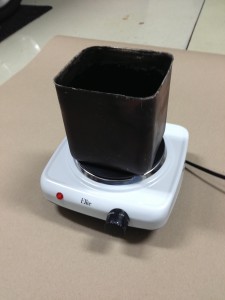
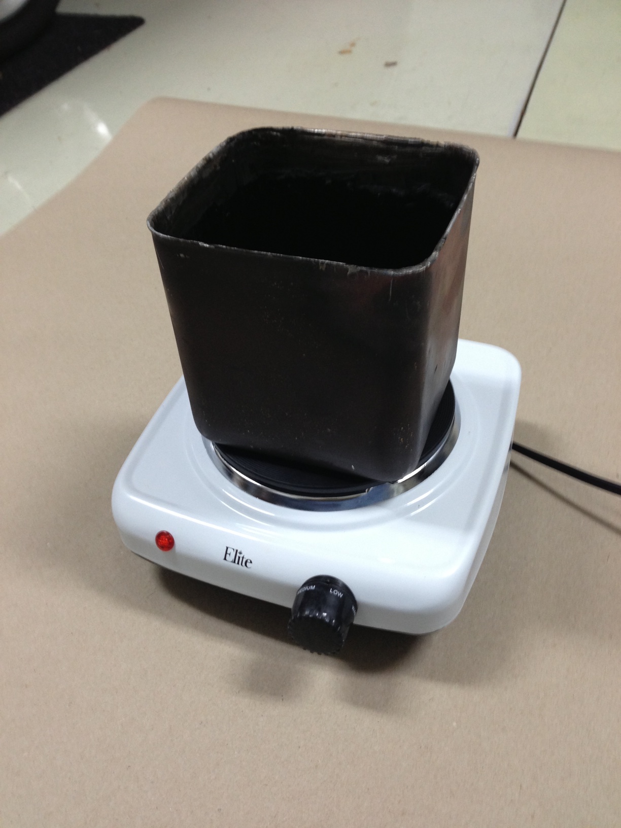
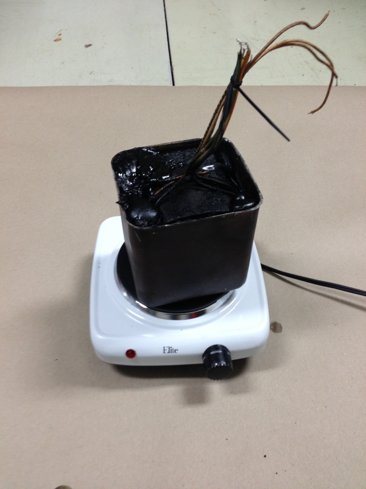
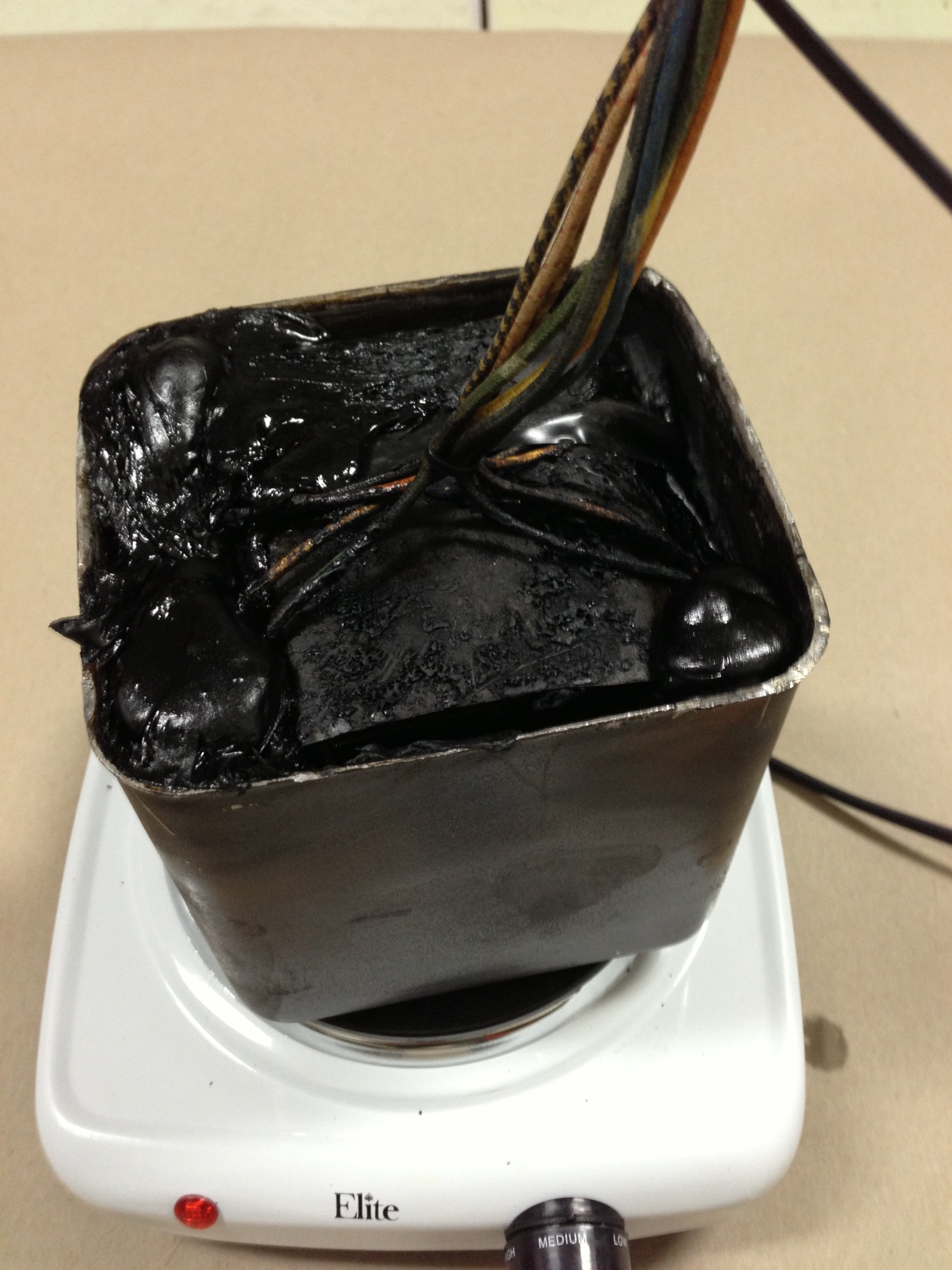
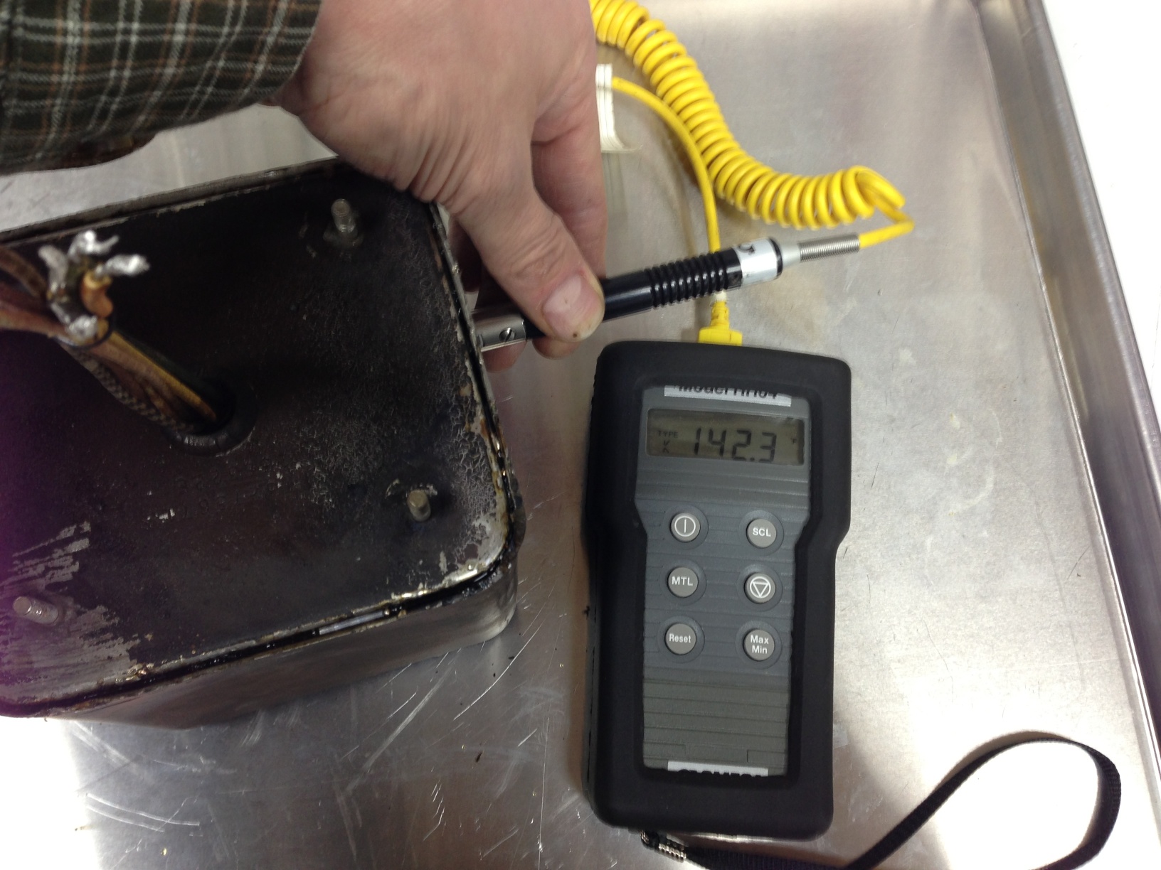
I taped up the protective paper wrapping that I removed (not as cleanly as I’d have hoped), and formulated a plan for re-potting.  My first thought was to set the transformer back in the can, and melt the tar in a pan and pour it back in.  I then realized that the can itself makes a dandy pan.  So I put all the tar pieces in the can, and set the can on a hotplate set on as low a temperature as it would go.  The tar started to soften and I set the transformer on top of the pile of softening tar.  As the tar continued to soften, the transformer sunk into the melting tar.  I pushed it to the bottom with a stick, and called the re-potting a success.  The final steps were to solder the lid back on and to fix the rim where I’d pounded it trying to get the lid off.  I filed down the marred areas of the rim, and then bondo-ed the region to smooth it out and hide my butchery.

IMG_3913


Category: Audio, kludge  | Tags: , , , , , ,  | Comments off
Tuesday, April 02nd, 2013 | Author:

IMG_3856

I broke down and bought a pair of Quad II amplifiers from eBay.  Like most of these old pieces of audio gear, the seller claimed no ability to test them and they were sold as is.  The pictures looked good, and the only thing missing was one fuse-holder cap.  I cleaned them up a bit and tested the tubes.  The original GEC KT66’s and the EF86’s all measured strong.  I through the switch on each amp and tested it on the bench. They seemed to be working well, so I gave them a listen.

They have that simple tube amplifier clarity, and warmth that keeps me coming back.  So at this point I decided to do a passive parts swap.  There isn’t an easy way to replace the power supply electrolytic caps, so I made a circuit board to hold a set of modern PCB caps.  The circuit boards are shown below:

IMG_3889

The amps really sound outstanding now, and are ready for a few more decades of use.

IMG_3895 IMG_3854 IMG_3851 IMG_3850

DSCF2036

IMG_2294

IMG_2295

Category: Audio  | Tags: , , , ,  | Comments off
Saturday, May 22nd, 2010 | Author:

The last high performance DAC I built is almost old enough to vote.  so I thought I should try building a new one given the new direction my audio addiction is taking.  My old Tube DAC still sounds fantastic to this day; in fact I’m still using the same prototype board that I etched in an apartment while in graduate school.  However being tube based, not only is it a bit of a power hog, but I don’t like to leave it on for long periods of time if I’m not using it.

My current audio system goals are to have small unobtrusive little speakers and electronics driven by streaming audio from my laptop or my server.  These systems should be powered up most all the time, and be as high performance as I can make.  I am finding that as I get older, I rarely just sit and listen to music, so a dedicated listening room largely sits empty.  Maybe I need to turn in my audiophile card, and get a Bose mini system; except I still appreciate and demand good sounding, low distortion , high fidelity music.

My current solution is to build high performance two-way speakers with high quality drivers, and drive them with digital switching amps which are very efficient and use very little power when idle.  The source for each of these little systems is an Apple Airport Express.  These little units let me stream my music as well as acting like little wireless routers and network extenders.  The sound quality from them is actually reasonably good, but it could be better.  They are welded shut during assembly, so there is no getting inside for some circuit improving, but in addition to analog output, they also output TOSLink optical digital signals as well.  This means that I can add a simple DAC between the Airport Express and one of my amps and improve my sound quality dramatically.

I had been toying with building a new DAC with Cirrus Logic chips (formerly Crystal Semiconductor) because the Crystal folks had consistently been making better and better sounding chips the last time I have checked into using them, and the Burr Brown offerings really dried up after Texas Instruments bought them.  I had played with asynchronous sample rate converters back in the AD1890 days, and they were a mixed bag sonically.  But I had read a great article at DIYAudio on how they work and why they can be very useful for digital audio.  Given that I am using a marginal TOSLink source, I thought that doing a bit of clean-up after the fact with one made some sense.  So I had picked out my chips:  CS8416 receiver, a CS8421 sample rate converter, and a CS4398 DAC.  After laboring over what to do with the needed analog stage, I got reading this enormous thread on a very inexpensive DAC on eBay.  If I had any brains, I would have just bought that DAC and called it good; well I did, but because I like to build things, I also made my own while I’ve been waiting for the DAC to arrive from China.

One of the major themes in that thread is using transformers as an analog stage for the DAC.  In general I find transformers to be nasty signal butchering devices, but maybe I’m getting more senile in my old age, but they appeal to me in that application.  The transformer is an ideal balanced to single ended converter, and the analog stage needs some filtering of ultrasonics, and the transformer does that as well.  For my application, I was also looking for something that would sound as good as my tube stage without the heat, power, and lifetime issues.  So I decided based on the glowing reports in the thread to give it a try.  But for good sound, just any old transformer won’t do.  I like the concept of circuit board mount transformers, and Lundahl has a great reputation for line level transformer sweetness.

Shown below is my first prototype.  It uses a pair of the LL1690 amorphous core line level transformers being fed by a CS4398 DAC, which is being fed by a CS8421 sample rate converter.  The converter gets it’s data from a CS8416 receiver with both coaxial and TOSLink inputs.  An Airport Express pushes bits through the TOSlink to the DAC.  The DAC uses a PCB mount toroidial power transformer which feeds seven discrete power supplies for the three chips.

I laid out the board expecting to send it off to a professional board house if it was worthy, but I don’t have deep enough pockets to just buy pro-made boards for every hair-brained circuit I generate.  I etch those myself.  So I reduced my 4 layer board to a double sided board with poured ground plane regions.  I’ve never etched a board this fine (TSSOP and 0604 parts), but somehow I did it.  Then it was a matter of soldering and squinting.

The schematic for the design is here:  DAC Schematic

The board layout is here:  DAC Board Layout

The parts list is here:  DAC Parts List

And now it’s time for some pictures:

Category: Audio, Macintosh  | Tags: , , , ,  | 5 Comments
Sunday, March 28th, 2010 | Author:

The Jordan JX-92 is a great little driver, but has some raggedness in the upper frequencies.  Below about 4KHz, the driver has a clarity and an uncolored response that is very impressive.  The bass response, while not window-rattling, is really impressive for a 5.5″ driver.  To take the good stuff from the Jordan and not get the bad, I decided to mate it up with a tweeter.  But not any old dome tweeter would do the Jordan justice.  I considered a ribbon, but I kept coming back to the Vifa XT-25 as a great mate for the Jordan.  The crossover point is nice and high, so the XT-25 won’t be stressed.  The character of the XT-25 also matches the Jordan driver quite nicely.  Finally, the deciding factor:  I had a pair of them.

The beginning of this project can be seen here:  http://getinthewoodchipper.com/?p=181 Where there are pictures of the cabinets being routed, and the drivers mounted.

The jordan is designed to not roll off in the treble, and the Vifa XT-25 doesn’t seem to know it’s tweeter.  So in order to get a reasonable crossover rate and not have a huge upper midrange muddying region where both drivers are contributing, the drivers need to be crossed over pretty hard.  After messing with 2nd order crossovers, it was pretty obvious that it wasn’t rolling the drivers off fast enough.  4th order filters worked pretty well, but the parts count was crazy, and the sound seemed somewhat pinched off and odd sounding in the crossover region.  I settled on a 3rd order crossover (electrical) for both the woofer and tweeter.  The woofer crossover is a butterworth topology, and the tweeter circuit is somewhat of an unknown that compliments the response of the woofer.

I used my computer and an external USB soundcard with my impedance bridge and microphone pre-amplifier, a Panasonic WM-61A electret microphone capsule, and my modified Dyna SCA-35 to drive the speaker as the basis of the measurement hardware to design the crossover.  I used two different software suites to do the driver response measurement.

I used Fuzzmeasure, which uses a swept-sine deconvolution to calculate the impulse response.  I also used software of my own design which uses MLS sequences to calculate the driver impulse response.  Fuzzmeasure is a very slick and easy to use program, but it seems to show a rosy picture of the response.   The drivers are in no way as flat as it makes them out to be, but the crossover region seems to be represented accurately.  Small changes in the crossover show up in the response.  Update:  I was over-driving my Fuzzmeasure measurements and that causes the flat-top readings shown below. My program is also slick and works the way I want it to, and I have control and understanding of the processing the program does.  My code also matches the impulse response of Loudspeaker Lab.

Here is the speaker response as measured with my software.  Note that my  impulse response is “windowed ” to eliminate the room response.  But the windowing process also rolls off the bass response, so anything below about 300Hz is artificially rolled off on the plots below.  The first plot is the impulse response, woofer and tweeter response, and the null from the tweeter polarity reversal.  The second plot shows the port contribution and woofer null with close microphone placement at the driver cone and port exit.  The red woofer trace shows the current port tuning at about 55Hz.  The Jordan is still breaking in, and I’ll lengthen the port to tune it to about 45Hz when the Fs of the Jordan drops.

The output of Fuzzmeasure is shown below.  Note the insane smoothness of the Jordan driver (compare this to every other measurement you’ve ever seen of the Jordan).  But the crossover information looks very similar.  Update:  The smoothness is due to over-driving my input signal, which was not obvious to me.  I’ve since fixed my problem and the Fuzzmeasure readings and my software readings agree very well.  Fuzzmeasure is a great Macintosh program for speaker and audio measurements.

Here’s some pictures of the crossover build-up process:

PCB Layout File:  jordan2way_crossoverPCB

Category: Audio  | Tags: , , , , ,  | Comments off