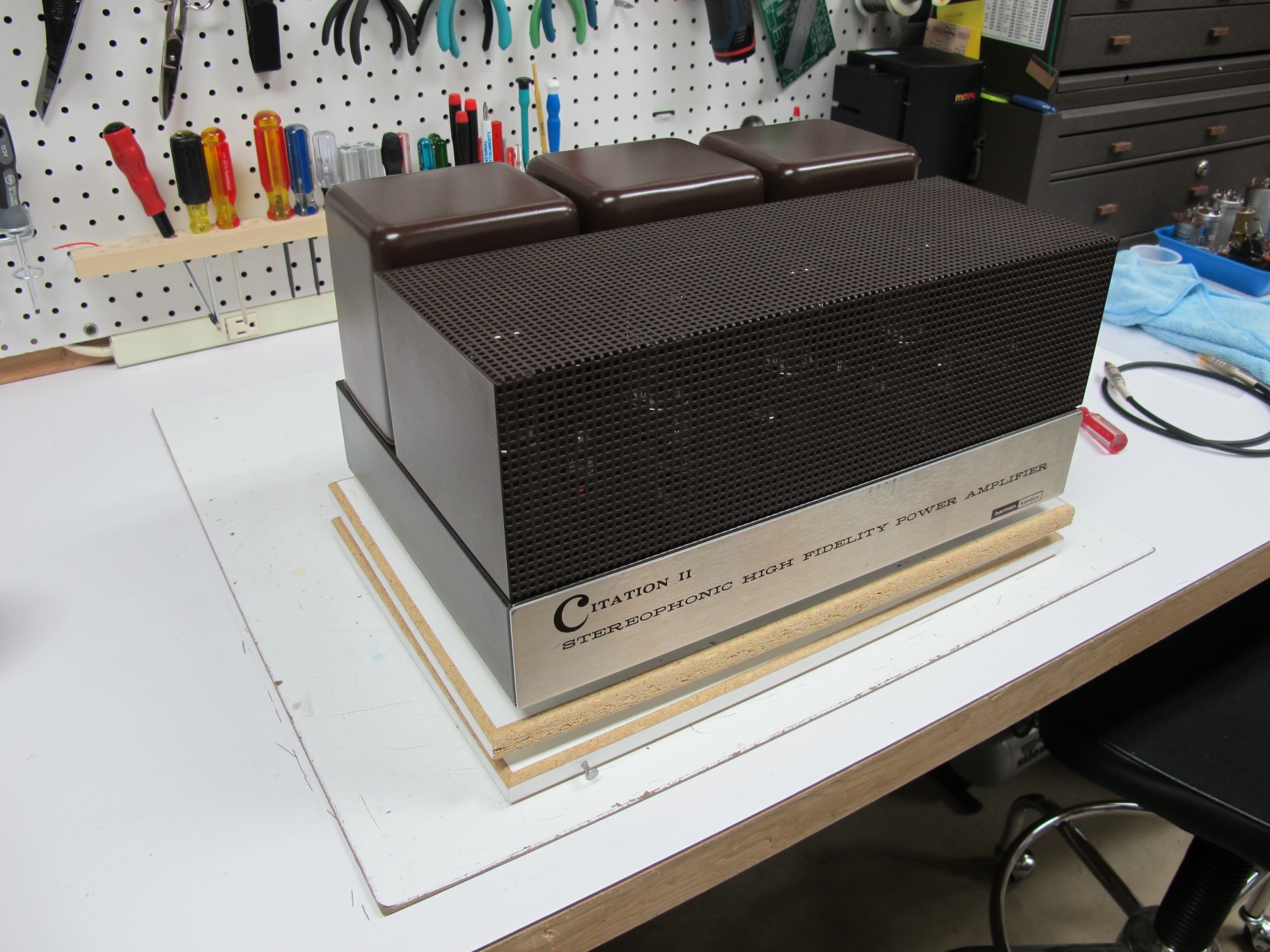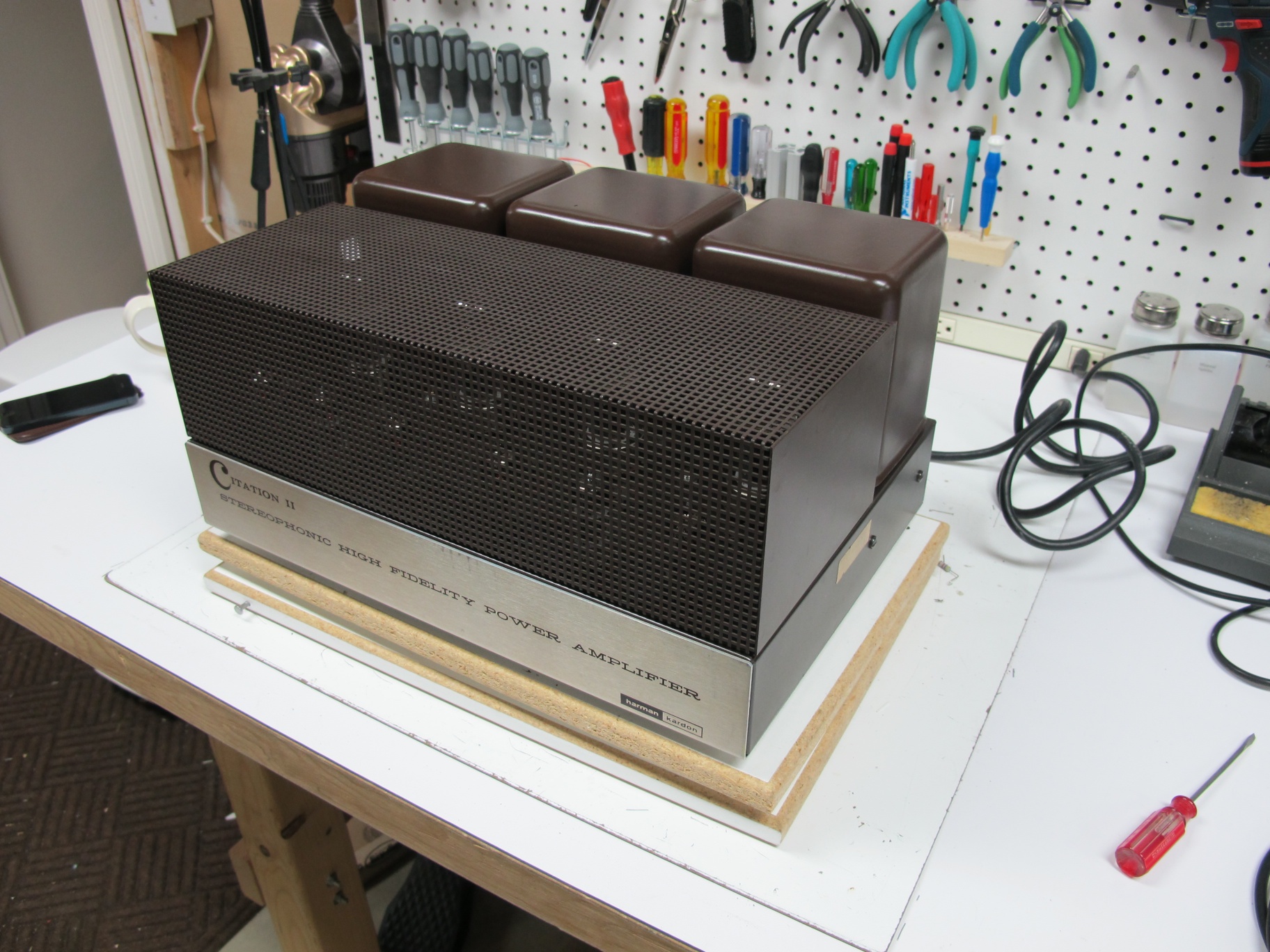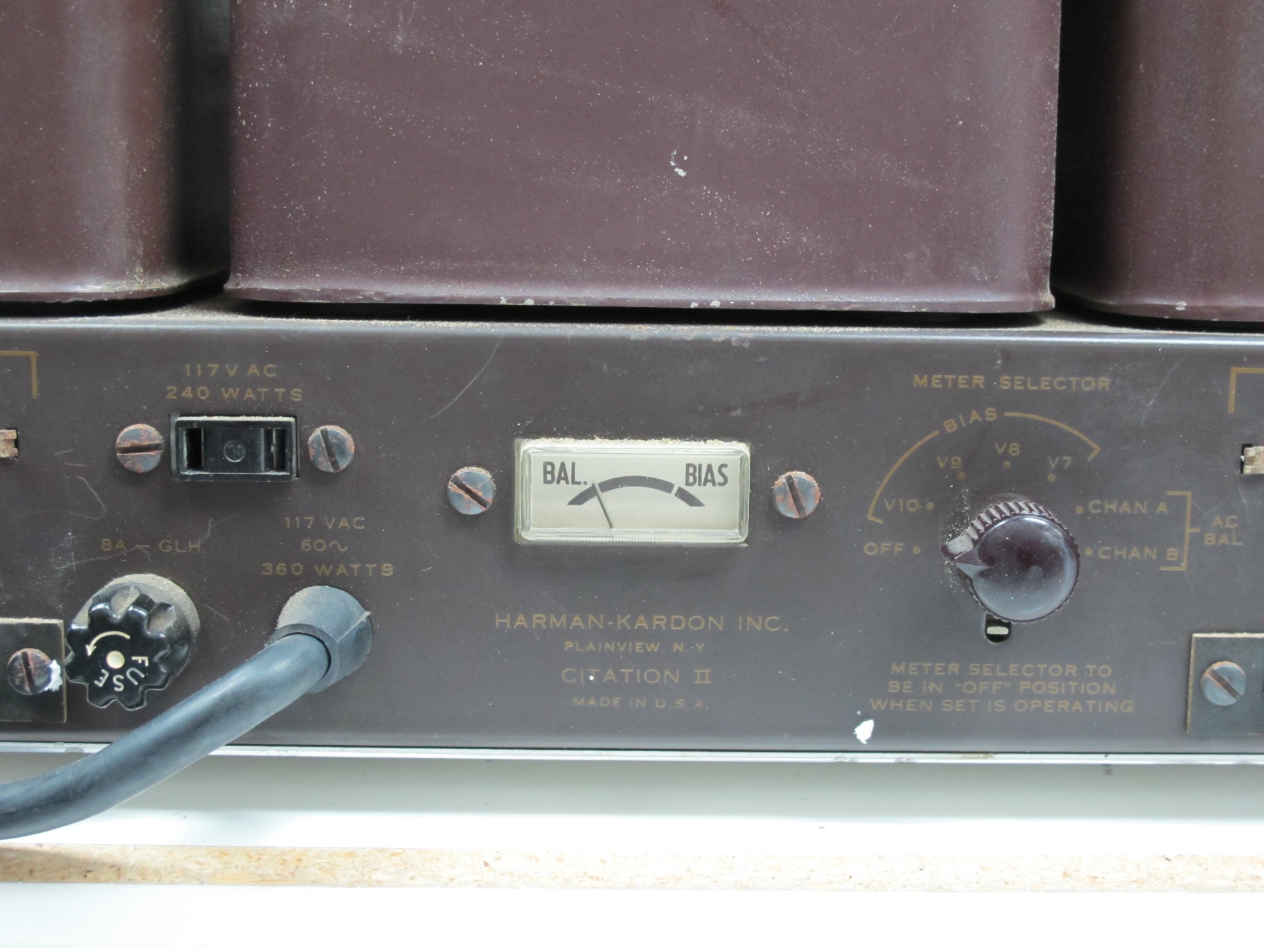
The Citation II is certainly a lovely amplifier, and has been a workhorse for me over the years. I’ve owned four of them to date. With every one of these that I have rebuilt, I’ve modified the bias meter circuit. The Citation II bias meter has two marks on it, an AC balance mark; which is the neutral needle position with no current input to the meter. The second mark is a “bias mark” which is the desired operating point for the tubes and is adjusted with four bias potentiometers. The two mark meter makes setting AC balance and DC bias un-ambiguous, but it doesn’t lead to any flexibility when using many modern tubes which require less plate power dissipation.
The DC bias portion of the meter circuit uses 15 ohm resistors inserted between each output tube’s cathode and ground. This “sense” resistor arrangement produces a voltage at the tube cathode that is proportional to the current through the tube via Ohm’s law (V =I * R). The meter circuit uses that voltage to move the needle.
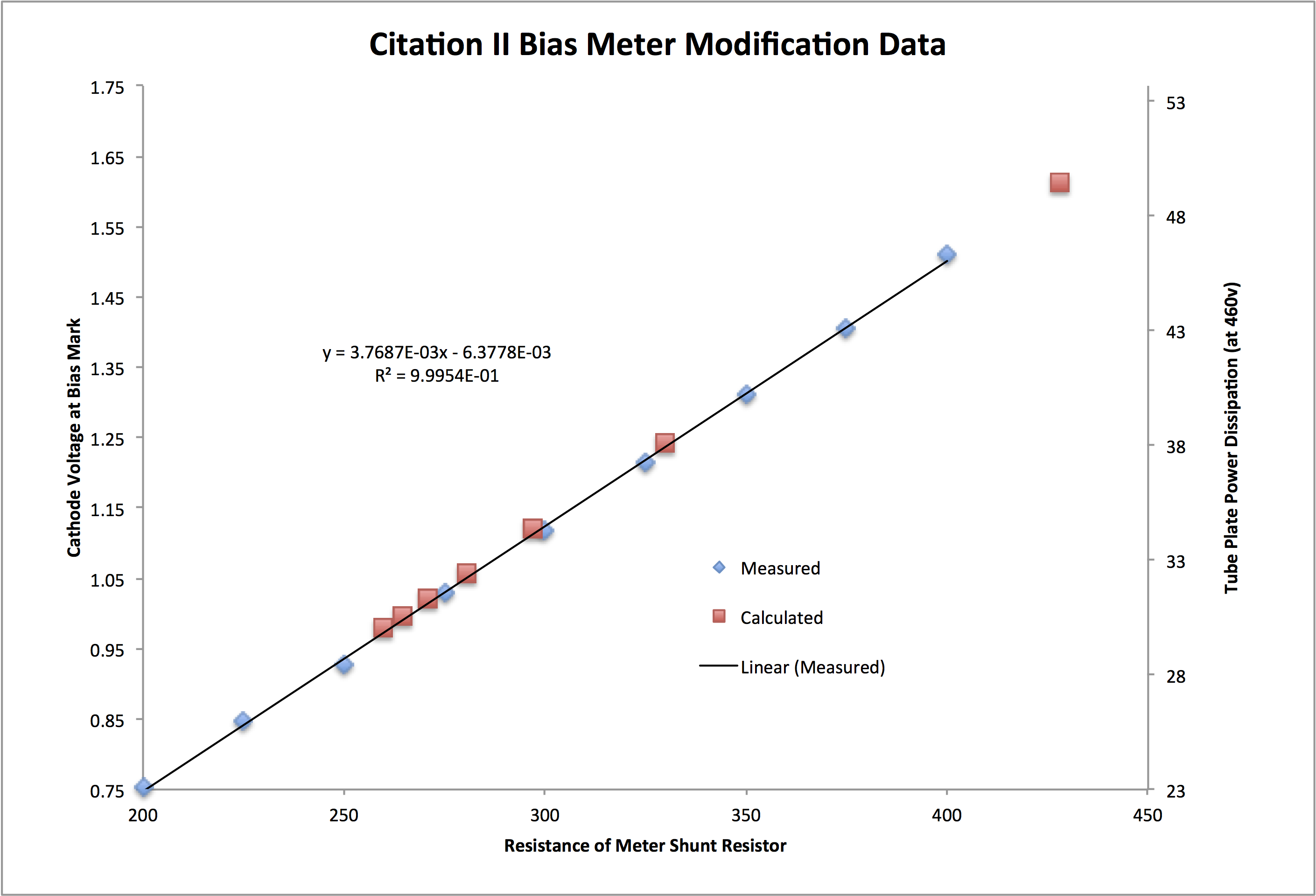
The meter itself is really an ammeter, in that the needle displacement is proportional to the current flowing through the meter coil. The coil resistance is really quite small. The current required to move the needle to the center of the bias mark in my meter is 3.77 mA. The meter circuit uses a series resistor to set the voltage versus needle position relationship. for example, if I wanted 1 volt across the meter to move the needle to the bias mark, I’d put a 265 ohm resistor in series with it.
The very early Citation II’s (which the Sam’s PhotoFacts seem to be based) had a 470 ohm resistor across the meter, so if the original (outside the chassis) meter had the same sensitivity, that would be a voltage of 1.77 volts. For the 15 ohm cathode resistors, that means that each output tube would have been drawing 118 mA for a plate dissipation (assuming a 460 volt B+) of 54 watts. I suspect that the original meter was less sensitive, but I have no way of knowing, as I’ve never owned a very early citation. The later internal meter units had 330 ohm resies resistors installed for a plate dissipation of 38 watts per tube. However, in an addendum to the assembly manual, HK suggests that the 330 ohm resistor be reduced to a 300 ohm one. This reduces the quiescent plate dissipation to 34.7 watts per tube. However this is still very close to the maximum allowable plate dissipation of many modern 6550 or KT88 tubes; for example the Svetlana 6550C has a max plate dissipation of 35 watts.
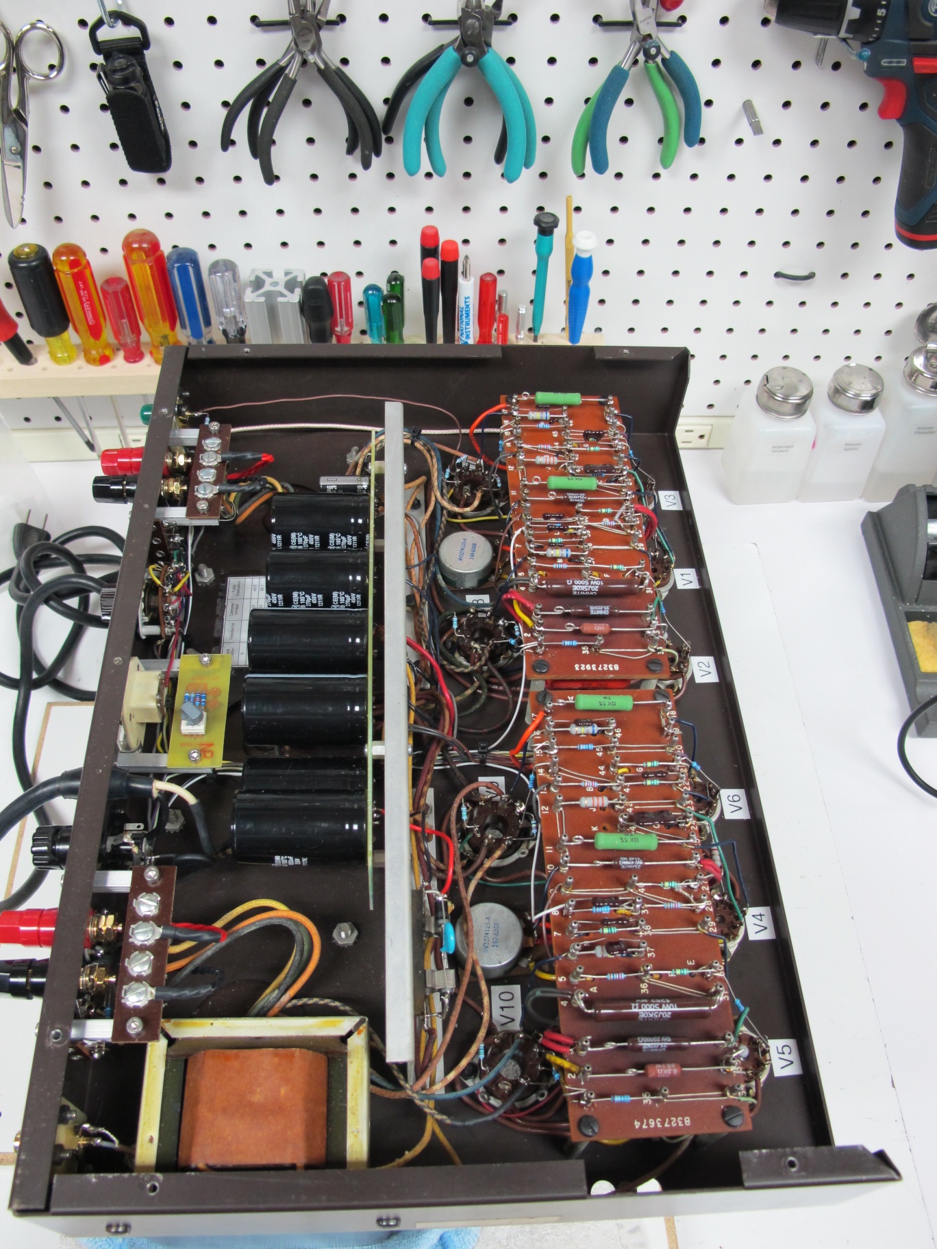
So in the past I’ve always changed that resistor to a smaller value to run 30-32 watts on the plates of the output tubes. Other references out on the web suggest changing the cathode resistors on the output tubes rather than change the series resistor in the meter circuit. Either will accomplish the same goal, but changing the cathode resistors requires changing four resistors instead of one, and they are much more difficult to get to. The output tube cathode resistors are buried between the power supply bracket and the input tag-boards.
The goal of the circuit shown above is to provide several settings for the bias meter that will not require soldering if the output tube brand or type is changed. The circuit uses a set of three resistors that are switched in and out of the circuit with a rotary octal switch and a fourth resistor in series. These resistors provide seven combinations of overall resistance that allow the meter bias point to be set to 6 usable positions from the stock (330 ohm) value down to 30 watts of plate dissipation.

Position 2 is the stock value, and position 3 is very close to the value specified in the addendum. Positions 4-7 allow a range of values to be selected for modern KT88 class tubes.
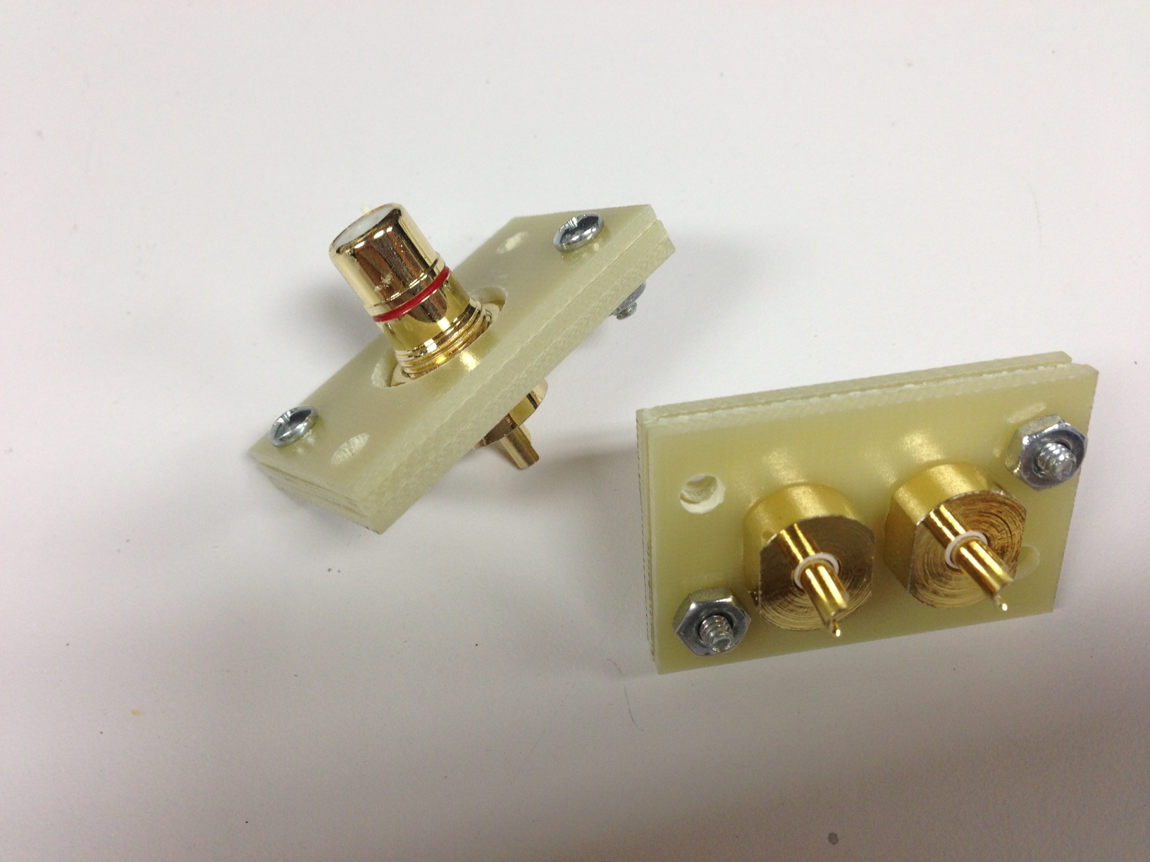
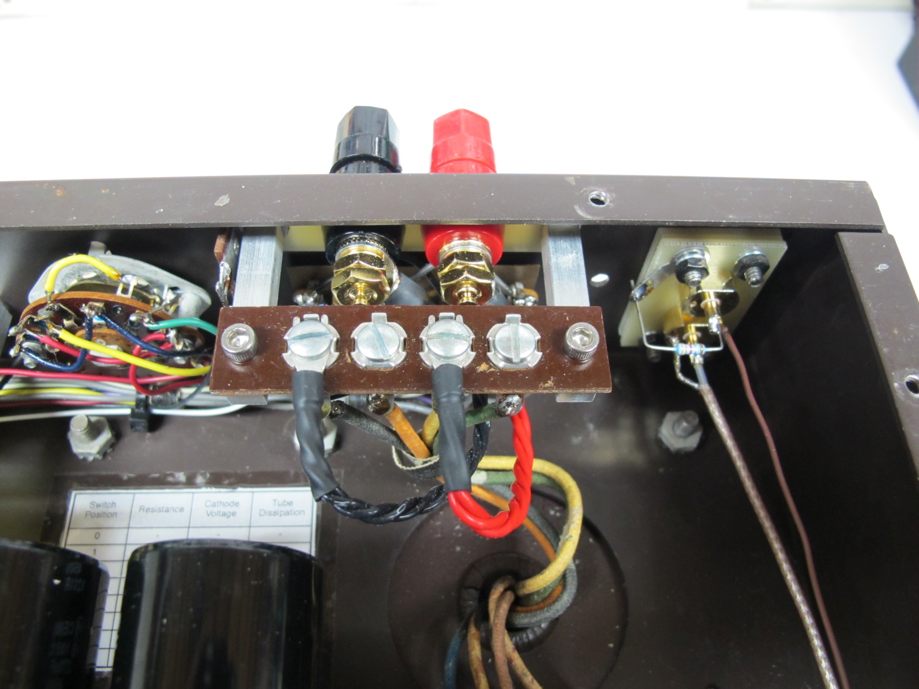
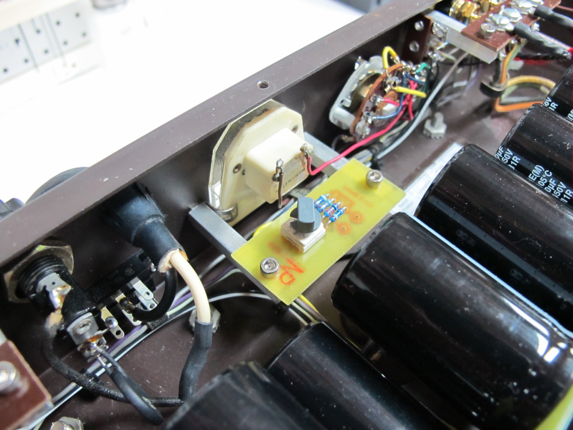
The board is held in place using the meter retention bolts and 1/4″ square section aluminum stock which has been tapped at one end and cross-drilled and tapped at the other (both tapped 6-32). This provides a secure mechanical mount for the meter adjustment circuit, etched onto a small circuit board. The layout and a simple schematic for this boar is show here: meterAdjustBoard
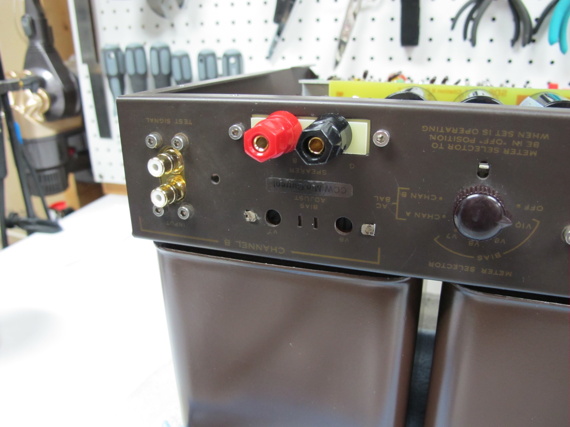
Changing of the meter range is as easy as flipping the amp over, removing the bottom cover, and turning the knob to the desired position. The table shown above was taped to the chassis to assist in setting the proper meter range. The advantage to having the circuit inside the amplifier is that no metalwork has been modified, and the amplifier can be returned to the stock configuration at any time.