Archive for » April, 2013 «

Sunday, April 28th, 2013 | Author:

IMG_2305

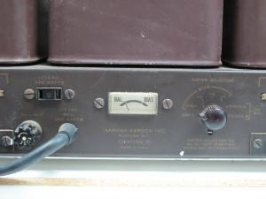
The Citation II is certainly a lovely amplifier, and has been a workhorse for me over the years.  I’ve owned four of them to date.  With every one of these that I have rebuilt, I’ve modified the bias meter circuit.  The Citation II bias meter has two marks on it, an AC balance mark; which is the neutral needle position with no current input to the meter.  The second mark is a “bias mark” which is the desired operating point for the tubes and is adjusted with four bias potentiometers.  The two mark meter makes setting AC balance and DC bias un-ambiguous, but it doesn’t lead to any flexibility when using many modern tubes which require less plate power dissipation.

The DC bias portion of the meter circuit uses 15 ohm resistors inserted between each output tube’s cathode and ground.  This “sense” resistor arrangement produces a voltage at the tube cathode that is proportional to the current through the tube via Ohm’s law (V =I * R).  The meter circuit uses that voltage to move the needle.

The meter itself is really an ammeter, in that the needle displacement is proportional to the current flowing through the meter coil.  The coil resistance is really quite small.  The current required to move the needle to the center of the bias mark in my meter is 3.77 mA.  The meter circuit uses a series resistor to set the voltage versus needle position relationship.  for example, if I wanted 1 volt across the meter to move the needle to the bias mark, I’d put a 265 ohm resistor in series with it.

The very early Citation II’s (which the Sam’s PhotoFacts seem to be based) had a 470 ohm resistor across the meter, so if the original (outside the chassis) meter had the same sensitivity, that would be a voltage of 1.77 volts.  For the 15 ohm cathode resistors, that means that each output tube would have been drawing 118 mA for a plate dissipation (assuming a 460 volt B+) of 54 watts.  I suspect that the original meter was less sensitive, but I have no way of knowing, as I’ve never owned a very early citation.  The later internal meter units had 330 ohm resies resistors installed for a plate dissipation of 38 watts per tube.  However, in an addendum to the assembly manual, HK suggests that the 330 ohm resistor be reduced to a 300 ohm one.  This reduces the quiescent plate dissipation to 34.7 watts per tube.  However this is still very close to the maximum allowable plate dissipation of many modern 6550 or KT88 tubes; for example the Svetlana 6550C has a max plate dissipation of 35 watts.

So in the past I’ve always changed that resistor to a smaller value to run 30-32 watts on the plates of the output tubes.  Other references out on the web suggest changing the cathode resistors on the output tubes rather than change the series resistor in the meter circuit.  Either will accomplish the same goal, but changing the cathode resistors requires changing four resistors instead of one, and they are much more difficult to get to.  The output tube cathode resistors are buried between the power supply bracket and the input tag-boards.

IMG_2362

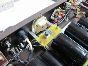
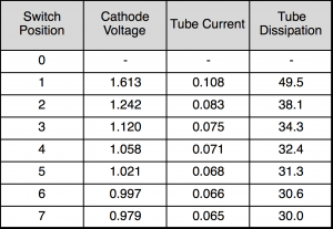
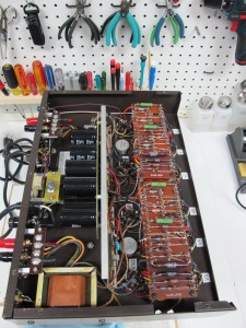
The goal of the circuit shown above is to provide several settings for the bias meter that will not require soldering if the output tube brand or type is changed.  The circuit uses a set of three resistors that are switched in and out of the circuit with a rotary octal switch and a fourth resistor in series.   These resistors provide seven combinations of overall resistance that allow the meter bias point to be set to 6 usable positions from the stock (330 ohm) value down to 30 watts of plate dissipation.

Citation2MeterChart

Position 2 is the stock value, and position 3 is very close to the value specified in the addendum.  Positions 4-7 allow a range of values to be selected for modern KT88 class tubes.

The board is held in place using the meter retention bolts and 1/4″ square section aluminum stock which has been tapped at one end and cross-drilled and tapped at the other (both tapped 6-32).  This provides a secure mechanical mount for the meter adjustment circuit, etched onto a small circuit board.  The layout and a simple schematic for this boar is show here:  meterAdjustBoard

Changing of the meter range is as easy as flipping the amp over, removing the bottom cover, and turning the knob to the desired position.  The table shown above was taped to the chassis to assist in setting the proper meter range.  The advantage to having the circuit inside the amplifier is that no metalwork has been modified, and the amplifier can be returned to the stock configuration at any time.

 

Citation2MeterModGraph

IMG_2387 IMG_2388

Sunday, April 28th, 2013 | Author:

The Harman Kardon Citation II is a great amplifier to be sure, but there are some limitations to the design.  One of the problems that has bothered me over the years are the terminal strips and the poor quality input jacks in the original design.  Many years ago I solved the input jack problem with new FR4 input boards that hold modern high-quality RCA jacks.

IMG_3886

IMG_3885

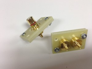
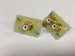
As seen in the photo’s above, a set of three layers of 1/16″ thick FR4 fiberglass was used to provide a platform to mount modern RCA jacks.  the four holes at the corners of the boards mate perfectly with the mounting holes in the Citation II chassis.  The bottom layer has smaller holes designed to accept the RCA jack and nut.  The next two layers act to space the mounting nut away from the amplifier chassis to prevent the RCA return connection from being shorted to the chassis.  This simple change allows high quality connections to the amplifier without modifying the metalwork of the amplifier at all.

IMG_2347IMG_2363


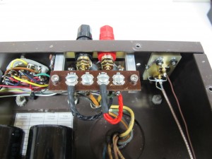
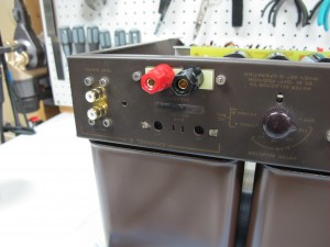
The second modification is aimed at making the speaker connections more reliable and easier to use with a variety of modern speaker cables.  The original amplifier terminal strip provides four connections for each speaker, a ground return and three different taps on the output transformer for three different nominal speaker impedances (4, 8, and 16 ohms).  The chassis cutout for this terminal strip is fairly small and would at most provide room for three connections.  My solution is to move the terminal strip inside the amplifier chassis and provide a pair of modern 5-way binding posts.  This was accomplished with a set of FR4 fiberglass spacers, much like the RCA jack spacers.  This time two layers of 1/16″ fiberglass was used.  The back layer is the same size as the original terminal strip and mounts tot he chassis using the same mounting points  The front layer acts purely as a spacer to account for the chassis thickness and allows the 5-way binding post bases to sit flush on the spacer rather than straddle the cutout in the chassis.

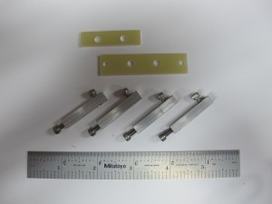
The set of spacers is held to the chassis by a bolt from the outside, and rather than a nut on the inside, a threaded bar is used.  This bar is made of 1/4″ square section aluminum bar stock, which is drilled and tapped (6-32) on one end and drilled and tap in the side at the opposite end as seen in the picture above.  This allows the bar to act as a nut to hold the 5-way binding post plates on the chassis and also provides a secure mounting point for the terminal strip inside the chassis as seen in the photo above.

The tweeter-saver components as mounted to the back of the terminal strip as they were in the stock amp, and the feedback and ground reference wires are attached to the back of the terminal strips as well.  However, the ground reference lead does not go tot he chassis as it did in the stock form; now it runs back to a common power supply ground.

A set of short leads with spade lugs on the end of them attaches the 5-way binding posts to the original terminal strips inside the amplifier.  The means that to change speaker taps, the amplifier has to be inverted and the 5-way binding post wire moved to the appropriate lug on the terminal strip.  However, in return for the inconvenience, the amplifier speaker connections are more robust and useful with many modern speaker cables.  And the chassis metalwork is never touched.

IMG_2378

IMG_2375

Tuesday, April 16th, 2013 | Author:

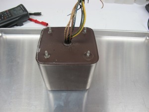
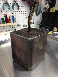
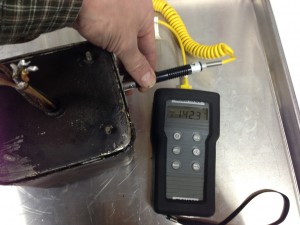
I bought a Harman Kardon Citation II Tube amplifier (my forth I’ve owned over my lifetime) from eBay. As is common, the previous owner chose not to, or didn’t know, the condition of the amplifier when he sold it.  I took a risk and bought it, as it looked to be in nice shape and I was taken in by the included tube cage.  Upon receiving it, I opened the bottom and measured the transformers.  One screen grid lead had high and inconsistent readings.  At first it was 20 kOhms, then it tropped to 4 kOhms, then down to about 50 Ohms, and back up.  Wiggling the wires coming out of the transformer didn’t change the reading at all.  I knew the worst, there was a fault somewhere inside the metal can, which is filled with tar.

IMG_2320

I really had nothing to lose, so I decided to get out the torch and see what was inside the can. I didn’t think I could actually fix the transformer, but not trying is admitting defeat.

The trick is figuring out how to get into the potted case to the transformer itself.  The top and sides of the can are drawn and are a single unit.  The bottom is a second piece and I suspected was stamped so that it had short sides that nested inside the body of the can.  The seam is then soldered.

It was unclear if the mounting studs for the transformer can also passed through the transformer laminations.  If the mounting studs also held the transformer, then the top of the can would slide off the transformer, if not, then the bottom would come off by itself.  I scritched and scratched around the mounting studs with a scribe to try to find a gap which would indicate that the bottom plate is slipped over the studs late in manufacturing.  I didn’t find any such gap, so I assumed that the studs were press fit into the bottom cover.

IMG_2344

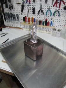
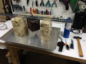
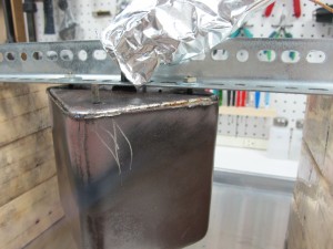
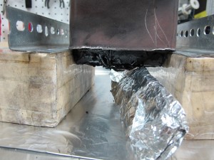
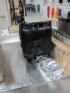
The first step is to suck out as much solder as I could.  I took a small oxy-propane torch and a vacuum pump as well as a solder catch can.  The catch can is a glass bottle with a plastic lid.  I drilled two holes in the plastic lid for two pieces of aquarium tubing.  One of the pieces of tubing is hooked to the vacuum pump, and the other piece of tubing is attached to a piece of stainless tubing.  The torch is used to locally soften the solder and with my other hand, I would suck it out of the crack with the tubing.  The transformer has so much thermal mass, that without a huge torch, there’s no hope of melting the solder all the way around.  If I could have added that much heat, I would be risking the transformer insulation.  So I relied on localized heating.  The photo to the left shows the transformer with the solder sucked out as best as I could.  The aluminum foil is actually two layers of foil with a damp paper towel sandwiched between them.  This prevents the leads being damaged if I am not careful with the flame.
IMG_3897IMG_2324

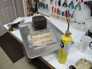
Shown above is the transformer with the solder removed and I’m in the process of trying to soften the remaining solder so the lid comes off.  I’ve switched from the very hot and localized oxy-propane torch to a simple propane torch, which has a much larger and cooler flame.  I was hoping that the larger flame would allow more even heating of the seam area and would free the lid.  I did some hammering on the seam as well, which I shouldn’t have, but I wasn’t sure if it was press fit or not.  It turns out that the solder seam was deeper and more extensive that I had guessed.
IMG_3899


IMG_2329


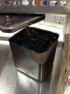
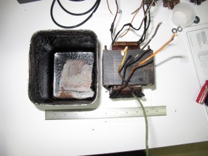
After a lot of heating around the seam area, the transformer can dropped onto the tray with a big thump.  My worst fears were realized, it was full of tar, and it smelled awful.  With the lid off, I could see that I had more work to do, because the transformer was still stuck in the can under all that tar.

IMG_2331IMG_2332

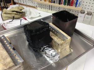
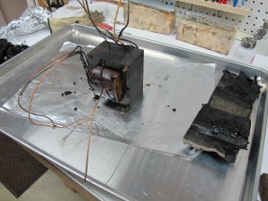
I flipped the transformer over and supported it on the edges of the can using some angle iron.  The tar wasn’t coming out at all because the tar at the top (bottom) of the can wasn’t hot enough to be liquid.  So I pulled out a third torch, which is a big mapp gas unit with a very broad rosebud type of flame that is ideal for gently heating a large area.  As I heated, the guts of the can slowly slid out onto the tray.


IMG_3900IMG_3901IMG_2335


The potting tar doesn’t completely fill the can.  The top of the can had no potting compound at all, as apparently most do not.  If you tap on the top of a mounted transformer it sounds hollow, an indication that there is no tar on that face.  The transformer has a band of insulating paper around it along the long two axes.  However, the tar has permeated in around the paper.

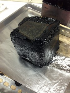
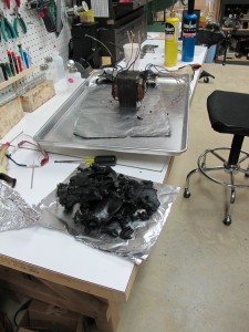
Fortunately, the tar has a nice property, if it’s cold, it’s hard as a rock (too hard to be a good potting compound), and if it’s really hot, it’s a liquid.  But in between those temperatures, it’s a soft putty consistency.  The process of softening the tar up enough to slide out of the can, left the bulk of the tar in that nice plastic state.  It was easy to peel it away from the transformer and it left the transformer really quite clean.

IMG_2343

IMG_2337

IMG_2338

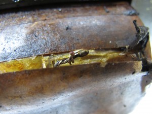
Now it was the moment of truth, time to find the fault.  I attached my multimeter to the primary center tap and the offended screen grid lead.  The resistance was now about 25 kOhms, a new value.  I poked the insulating wrap where the screen grid lead goes in, and bam, open circuit.  I poked some more and got another high resistance reading.  That was really good news, as the fault was right at the surface.  The figure below shows the fault exposed.

IMG_2341

The fault is the transformer copper wire melted away from the stranded wire lead that exits the transformer body.  I suspect this is a common fault point because there is a natural air pocket there.  The bulk of the windings have a lot of contact area with the neighboring windings and also to the insulating material on either side.  But the exit point doesn’t have that luxury for heat transfer, and apparently it overheated and melted back from the contact point.  Something serious happened to the screen grid of that output tube.  There was some melt products that formed a carbon comp resistor, that I was measuring with my meter before I tore the transformer open.  After repairing the joint by cleaning and soldering, it was time to reverse the process.  The problem is that the tar was now as hard as a rock.


IMG_3909
IMG_3910

IMG_3911 IMG_3912

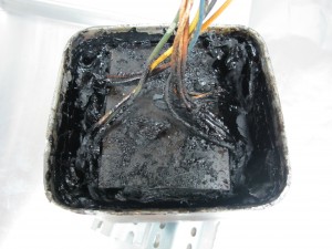
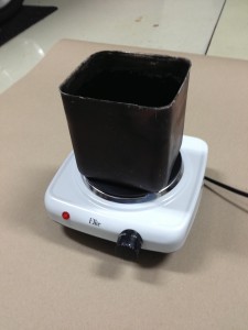
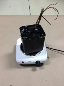
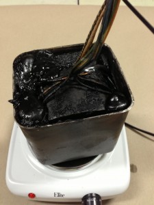
I taped up the protective paper wrapping that I removed (not as cleanly as I’d have hoped), and formulated a plan for re-potting.  My first thought was to set the transformer back in the can, and melt the tar in a pan and pour it back in.  I then realized that the can itself makes a dandy pan.  So I put all the tar pieces in the can, and set the can on a hotplate set on as low a temperature as it would go.  The tar started to soften and I set the transformer on top of the pile of softening tar.  As the tar continued to soften, the transformer sunk into the melting tar.  I pushed it to the bottom with a stick, and called the re-potting a success.  The final steps were to solder the lid back on and to fix the rim where I’d pounded it trying to get the lid off.  I filed down the marred areas of the rim, and then bondo-ed the region to smooth it out and hide my butchery.

IMG_3913


Category: Audio, kludge  | Tags: , , , , , ,  | Comments off
Tuesday, April 02nd, 2013 | Author:

IMG_3856

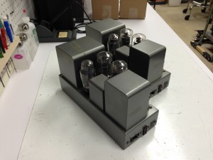
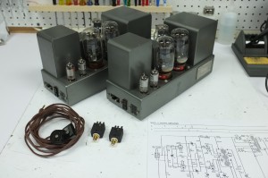
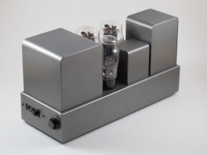
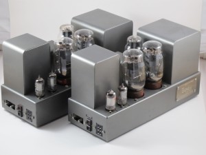
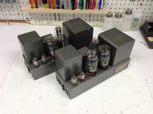
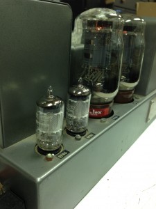
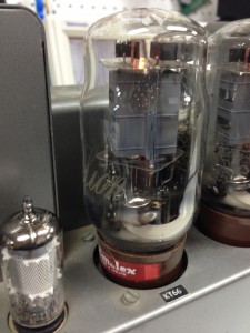
I broke down and bought a pair of Quad II amplifiers from eBay.  Like most of these old pieces of audio gear, the seller claimed no ability to test them and they were sold as is.  The pictures looked good, and the only thing missing was one fuse-holder cap.  I cleaned them up a bit and tested the tubes.  The original GEC KT66’s and the EF86’s all measured strong.  I through the switch on each amp and tested it on the bench. They seemed to be working well, so I gave them a listen.

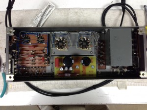
They have that simple tube amplifier clarity, and warmth that keeps me coming back.  So at this point I decided to do a passive parts swap.  There isn’t an easy way to replace the power supply electrolytic caps, so I made a circuit board to hold a set of modern PCB caps.  The circuit boards are shown below:

IMG_3889

The amps really sound outstanding now, and are ready for a few more decades of use.

IMG_3895 IMG_3854 IMG_3851 IMG_3850

DSCF2036

IMG_2294

IMG_2295

Category: Audio  | Tags: , , , ,  | Comments off