Archive for » 2010 «

Tuesday, June 29th, 2010 | Author:
The Dyna ST-70 is probably the most prolific tube amp, and it’s a solid performer at what used to be a reasonable price.  I got my first one out of a dumpster for free in 1992.  At that time and the decade before, $50 would get you a reasonable sample.  However, today there are a variety of choices that didn’t exist at the time I got my first Dyna amp; choices like Class D and Tripath amps, Chinese tube amps for a fraction of the price of domestic ones, and a large DIY community with many great solid state designs.
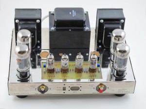
The Dyna ST-70 is a very balanced design, with very good output iron for the amps price-point.  But the input section is a compromise and can be improved upon.  I re-drew the Triode electronics design that was lost in their fire many years ago.  I’ve offered up the artwork on my site for many years, and triode electronics has been selling it for many years.  I have never been in love with the design due to the odd number of tubes.  The ST-70 has separate filament windings for each channel.  So with an odd number of tubes, one channel has more filament load than the other channel.
So fast forwarding a couple decades, there are Dyna clones from a couple of manufacturers, and more input board options than ever.  So there’s really no reason for me to have designed and built another one, but I did it anyway.
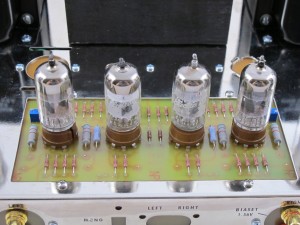
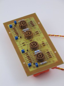
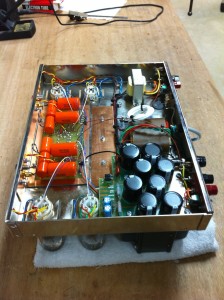
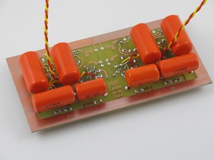
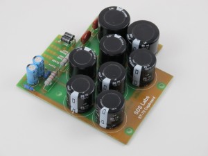
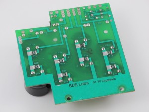
This input board is slightly different than the others I’ve seen.  First the voltage gain stage is a paralleled 12AT7 dual triode.  That stage feeds a long tail pair phase splitter.  The phase splitter has a balance adjustment potentiometer.  Each output tube has it’s own bias adjustment potentiometer as well.  This input board is a nice compliment to the power supply board that is on my site as well.  The input board area is fairly small to accommodate a four tube circuit and the requisite coupling caps and other parts.  So to get around this limitation, the coupling capacitors are installed under the board.  All the resistors and other components are installed on the top of the board with the tubes.
So how does it sound?  Well, when combined with my capboard and using the Triode Electronics Dynaclone transformers, the amplifier has the typical clean and distortion midrange and treble, with bass authority that the stock Dyna ST-70 circuit cannot match.  I don’t have an actual Dyna ST-70 at the moment, so I can’t do a direct comparison, but this unit is performing remarkably well both on the bench and through my ESL63’s.  In the bench, this amp passes picture perfect square waves at 10Hz (2 watts), and is flat out to 80KHz (2 watts) with a small ringing at the leading and falling edges.

Here is the schematic:   Schematic

Here is the Layout:  Layout


Category: Audio  | Tags: , , , ,  | One Comment
Saturday, May 22nd, 2010 | Author:

The last high performance DAC I built is almost old enough to vote.  so I thought I should try building a new one given the new direction my audio addiction is taking.  My old Tube DAC still sounds fantastic to this day; in fact I’m still using the same prototype board that I etched in an apartment while in graduate school.  However being tube based, not only is it a bit of a power hog, but I don’t like to leave it on for long periods of time if I’m not using it.

My current audio system goals are to have small unobtrusive little speakers and electronics driven by streaming audio from my laptop or my server.  These systems should be powered up most all the time, and be as high performance as I can make.  I am finding that as I get older, I rarely just sit and listen to music, so a dedicated listening room largely sits empty.  Maybe I need to turn in my audiophile card, and get a Bose mini system; except I still appreciate and demand good sounding, low distortion , high fidelity music.

My current solution is to build high performance two-way speakers with high quality drivers, and drive them with digital switching amps which are very efficient and use very little power when idle.  The source for each of these little systems is an Apple Airport Express.  These little units let me stream my music as well as acting like little wireless routers and network extenders.  The sound quality from them is actually reasonably good, but it could be better.  They are welded shut during assembly, so there is no getting inside for some circuit improving, but in addition to analog output, they also output TOSLink optical digital signals as well.  This means that I can add a simple DAC between the Airport Express and one of my amps and improve my sound quality dramatically.

I had been toying with building a new DAC with Cirrus Logic chips (formerly Crystal Semiconductor) because the Crystal folks had consistently been making better and better sounding chips the last time I have checked into using them, and the Burr Brown offerings really dried up after Texas Instruments bought them.  I had played with asynchronous sample rate converters back in the AD1890 days, and they were a mixed bag sonically.  But I had read a great article at DIYAudio on how they work and why they can be very useful for digital audio.  Given that I am using a marginal TOSLink source, I thought that doing a bit of clean-up after the fact with one made some sense.  So I had picked out my chips:  CS8416 receiver, a CS8421 sample rate converter, and a CS4398 DAC.  After laboring over what to do with the needed analog stage, I got reading this enormous thread on a very inexpensive DAC on eBay.  If I had any brains, I would have just bought that DAC and called it good; well I did, but because I like to build things, I also made my own while I’ve been waiting for the DAC to arrive from China.

One of the major themes in that thread is using transformers as an analog stage for the DAC.  In general I find transformers to be nasty signal butchering devices, but maybe I’m getting more senile in my old age, but they appeal to me in that application.  The transformer is an ideal balanced to single ended converter, and the analog stage needs some filtering of ultrasonics, and the transformer does that as well.  For my application, I was also looking for something that would sound as good as my tube stage without the heat, power, and lifetime issues.  So I decided based on the glowing reports in the thread to give it a try.  But for good sound, just any old transformer won’t do.  I like the concept of circuit board mount transformers, and Lundahl has a great reputation for line level transformer sweetness.

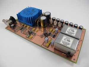
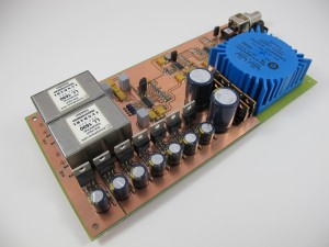
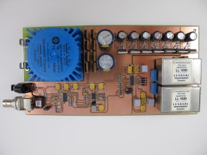
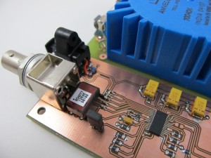
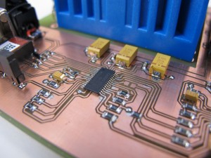
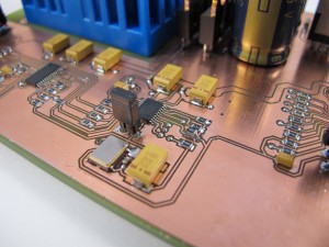
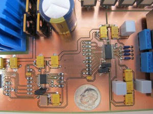
Shown below is my first prototype.  It uses a pair of the LL1690 amorphous core line level transformers being fed by a CS4398 DAC, which is being fed by a CS8421 sample rate converter.  The converter gets it’s data from a CS8416 receiver with both coaxial and TOSLink inputs.  An Airport Express pushes bits through the TOSlink to the DAC.  The DAC uses a PCB mount toroidial power transformer which feeds seven discrete power supplies for the three chips.

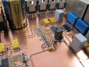
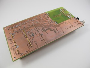
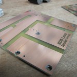
I laid out the board expecting to send it off to a professional board house if it was worthy, but I don’t have deep enough pockets to just buy pro-made boards for every hair-brained circuit I generate.  I etch those myself.  So I reduced my 4 layer board to a double sided board with poured ground plane regions.  I’ve never etched a board this fine (TSSOP and 0604 parts), but somehow I did it.  Then it was a matter of soldering and squinting.

The schematic for the design is here:  DAC Schematic

The board layout is here:  DAC Board Layout
The parts list is here:  DAC Parts List

And now it’s time for some pictures:

Category: Audio, Macintosh  | Tags: , , , ,  | 5 Comments
Sunday, March 28th, 2010 | Author:

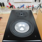
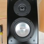
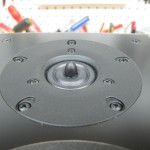
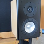
The Jordan JX-92 is a great little driver, but has some raggedness in the upper frequencies.  Below about 4KHz, the driver has a clarity and an uncolored response that is very impressive.  The bass response, while not window-rattling, is really impressive for a 5.5″ driver.  To take the good stuff from the Jordan and not get the bad, I decided to mate it up with a tweeter.  But not any old dome tweeter would do the Jordan justice.  I considered a ribbon, but I kept coming back to the Vifa XT-25 as a great mate for the Jordan.  The crossover point is nice and high, so the XT-25 won’t be stressed.  The character of the XT-25 also matches the Jordan driver quite nicely.  Finally, the deciding factor:  I had a pair of them.

The beginning of this project can be seen here:  http://getinthewoodchipper.com/?p=181 Where there are pictures of the cabinets being routed, and the drivers mounted.

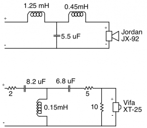
The jordan is designed to not roll off in the treble, and the Vifa XT-25 doesn’t seem to know it’s tweeter.  So in order to get a reasonable crossover rate and not have a huge upper midrange muddying region where both drivers are contributing, the drivers need to be crossed over pretty hard.  After messing with 2nd order crossovers, it was pretty obvious that it wasn’t rolling the drivers off fast enough.  4th order filters worked pretty well, but the parts count was crazy, and the sound seemed somewhat pinched off and odd sounding in the crossover region.  I settled on a 3rd order crossover (electrical) for both the woofer and tweeter.  The woofer crossover is a butterworth topology, and the tweeter circuit is somewhat of an unknown that compliments the response of the woofer.

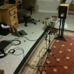
I used my computer and an external USB soundcard with my impedance bridge and microphone pre-amplifier, a Panasonic WM-61A electret microphone capsule, and my modified Dyna SCA-35 to drive the speaker as the basis of the measurement hardware to design the crossover.  I used two different software suites to do the driver response measurement.

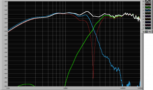
I used Fuzzmeasure, which uses a swept-sine deconvolution to calculate the impulse response.  I also used software of my own design which uses MLS sequences to calculate the driver impulse response.  Fuzzmeasure is a very slick and easy to use program, but it seems to show a rosy picture of the response.   The drivers are in no way as flat as it makes them out to be, but the crossover region seems to be represented accurately.  Small changes in the crossover show up in the response.  Update:  I was over-driving my Fuzzmeasure measurements and that causes the flat-top readings shown below. My program is also slick and works the way I want it to, and I have control and understanding of the processing the program does.  My code also matches the impulse response of Loudspeaker Lab.

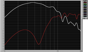
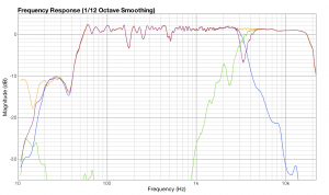
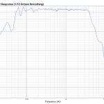
Here is the speaker response as measured with my software.  Note that my  impulse response is “windowed ” to eliminate the room response.  But the windowing process also rolls off the bass response, so anything below about 300Hz is artificially rolled off on the plots below.  The first plot is the impulse response, woofer and tweeter response, and the null from the tweeter polarity reversal.  The second plot shows the port contribution and woofer null with close microphone placement at the driver cone and port exit.  The red woofer trace shows the current port tuning at about 55Hz.  The Jordan is still breaking in, and I’ll lengthen the port to tune it to about 45Hz when the Fs of the Jordan drops.

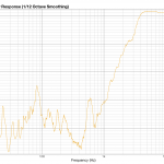
The output of Fuzzmeasure is shown below.  Note the insane smoothness of the Jordan driver (compare this to every other measurement you’ve ever seen of the Jordan).  But the crossover information looks very similar.  Update:  The smoothness is due to over-driving my input signal, which was not obvious to me.  I’ve since fixed my problem and the Fuzzmeasure readings and my software readings agree very well.  Fuzzmeasure is a great Macintosh program for speaker and audio measurements.

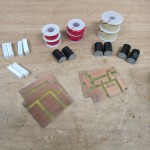
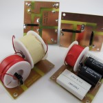
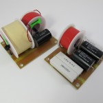
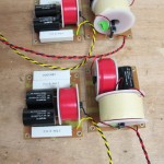
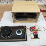
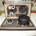
Here’s some pictures of the crossover build-up process:

PCB Layout File:  jordan2way_crossoverPCB
Category: Audio  | Tags: , , , , ,  | Comments off
Tuesday, March 16th, 2010 | Author:

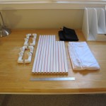
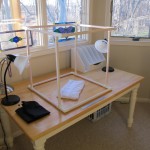
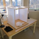
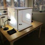
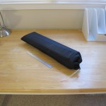
My wife has been lampworking glass beads and is starting to sell her wares.  In order to take pictures of her handiwork, I needed a good way to illuminate the small glass artwork.  There are many plans for simple lightboxes based on cardboard boxes on the web, but I just can’t bring myself to build any tool that I’m going to use for more than a few minutes out of cardboard.  So I built one out of 1/2″ PVC pipe and some stretchy white nearly swimsuit material.  The whole thing breaks down and stows into a canvas bag that I sewed for the purpose.  The box is sized to accept 22″ wide posterboard without cutting to act as a seamless background.  I light the box with a pair of 100 watt daylight compact fluorescent bulbs in desk lamps.   The total cost of the light box is about $12.
Category: Photography  | Tags: , ,  | Comments off
Tuesday, March 16th, 2010 | Author:

I’ve been building speakers for myself and others as well as repairing Quad Electrostatic speakers for nearly twenty years.  A couple of my designs are shown on my website, as well as instructions and descriptions of how to repair the Quad ESLs.  One key tool needed in speaker design and repair is the ability to measure the speakers acoustical response.  I have used  Loudspeaker Lab to measure passive components, driver TS parameters, and speaker impulse response and sweeps.  Lately I’ve been using Fuzzmeasure on my Mac, which is a nice and simple package, and works well.  But nothing works exactly like you like to work except software you write yourself.  I have a complete passive component measuring, Driver TS parameter calculating, and speaker impulse and sweep response measuring suite written in LabView.  I’ll be posting a description of my software suite and lots of screenshots soon.

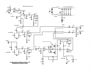
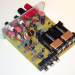
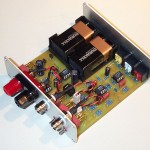
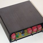
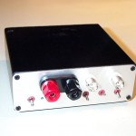
Regardless of the software used, a good microphone pre-amplifier is needed.  In 2002, I designed a measurement bridge loosely based on the Loudspeaker Lab box.  The controls were designed to match the Loudspeaker Lab box, and my measurement box contains a lot of the same functionality, but in a higher performance, more battery hungry version.  The measurement box contains a low noise wide bandwidth microphone pre-amp, an amplified impedance bridge, and an extra channel of buffering for amplifier compensation when measuring speakers.  In addition, I have a built in reference resistor (0.005%) to calibrate the impedance bridge.

This bridge allows me to measure and match crossover components (caps, resistors and inductors), measure driver Thiele-Small parameters (Delta Mass), and measure speakers; both impulse response (MLS based), and in-room sweeps.  I use this measurement box in conjunction with Panasonic WM-61A electret microphones.

Here is the schematic for my measurement bridge:

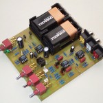
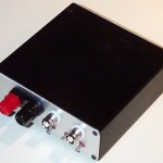
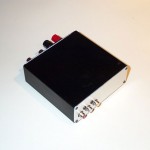
And here’s a few pictures of the measurement box itself.  It loves to eat 9V batteries:

Monday, March 15th, 2010 | Author:

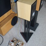
I’ve had a pair of Jordan JX-92S sitting around for a year or so (part of a DIYAudio group buy).  I built a set of transmission line speakers around these drivers several years ago, and while they are amazing drivers, they do have issues in the treble.   So given that I also have a pair of the very nice Vifa XT-25 tweeters that should mate nicely with the Jordan, these drivers should make a great little speaker.  The JX-92’s really work well in a transmission line or a quarter wave tube, but I was looking for a much smaller speaker.  The Jordan is an amazing driver, but it’s still a small 5 1/2″ driver.

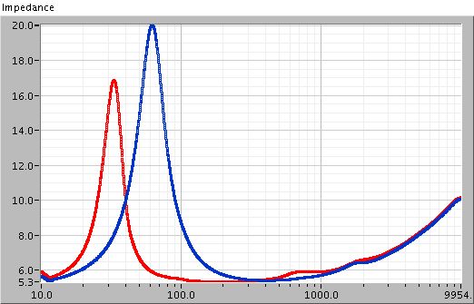
My measurements after a day of break-in show that the JX-92 has the following parameters:

Fs Qms Qes Qts Vas
62.0304 2.4919 0.8639 0.6415 7.8288
Re Mms no (%) Sp So
5.1570 7.2457 0.2076 85.3730 87.2273

The Fs is unusually high, which indicates that the driver is not yet fully broken in.  However the Q of the driver isn’t very far removed from what others are getting from these new “more efficient” JX-92 drivers.  The Q being so high is bad for my hopes of making a small speaker from this driver.  Based on these parameters, I need a 1.3cu-ft box if I was going to used a ported enclosure.  That’s a huge floor-standing box.  A transmission line would also be a slightly smaller floor-standing box.  A sealed enclosure would be small, and completely anemic.

As much as I like the Jordan drivers, A speaker with a 0.5 cu-ft enclosure or larger lends itself to a a whole other class of drivers.  For example in a 0.5 cu-ft vented box, the Zaph SR-71 speaker outclasses the jordan in every way (in the midrange down; with a driver that is 1/3 the cost of a jordan).  A floorstanding speaker lends itself to even more impressive driver and frequency extension.  So in order for the Jordan JX-92 to be a useful driver to me, it HAS to live in a small enclosure.

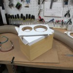
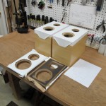
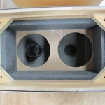
I bought a set of the Parts Express 0.25 cu-ft enclosures and have cut them into a set of ported enclosures.   I’ve got the port tuned for about 55 Hz at this point, but it should actually be a bit lower.  I’m considering trying an extended bass shelf design in this little enclosure.

The problem with this driver selection is that the woofer really is trying to be a tweeter, and the tweeter thinks it’s a woofer.  So I’m slapping both drivers down with third order crossovers.  It’s a good first cut, but not perfect.  Coming up will be the final crossover design and my Labview speaker measurement software in action.  I’m using Fuzzmeasure and my own software in a MacBook Pro with an M-Audio Transit USB soundcard.

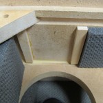
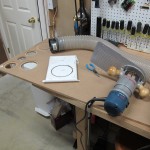
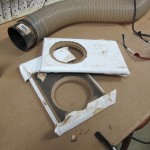
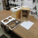
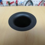
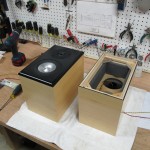
Below are some pictures of  the fabrication and some of the crossover design.