The Dyna ST-70 is probably the most prolific tube amp, and it’s a solid performer at what used to be a reasonable price. I got my first one out of a dumpster for free in 1992. At that time and the decade before, $50 would get you a reasonable sample. However, today there are a variety of choices that didn’t exist at the time I got my first Dyna amp; choices like Class D and Tripath amps, Chinese tube amps for a fraction of the price of domestic ones, and a large DIY community with many great solid state designs.
The Dyna ST-70 is a very balanced design, with very good output iron for the amps price-point. But the input section is a compromise and can be improved upon. I re-drew the Triode electronics design that was lost in their fire many years ago. I’ve offered up the artwork on my site for many years, and triode electronics has been selling it for many years. I have never been in love with the design due to the odd number of tubes. The ST-70 has separate filament windings for each channel. So with an odd number of tubes, one channel has more filament load than the other channel.
So fast forwarding a couple decades, there are Dyna clones from a couple of manufacturers, and more input board options than ever. So there’s really no reason for me to have designed and built another one, but I did it anyway.
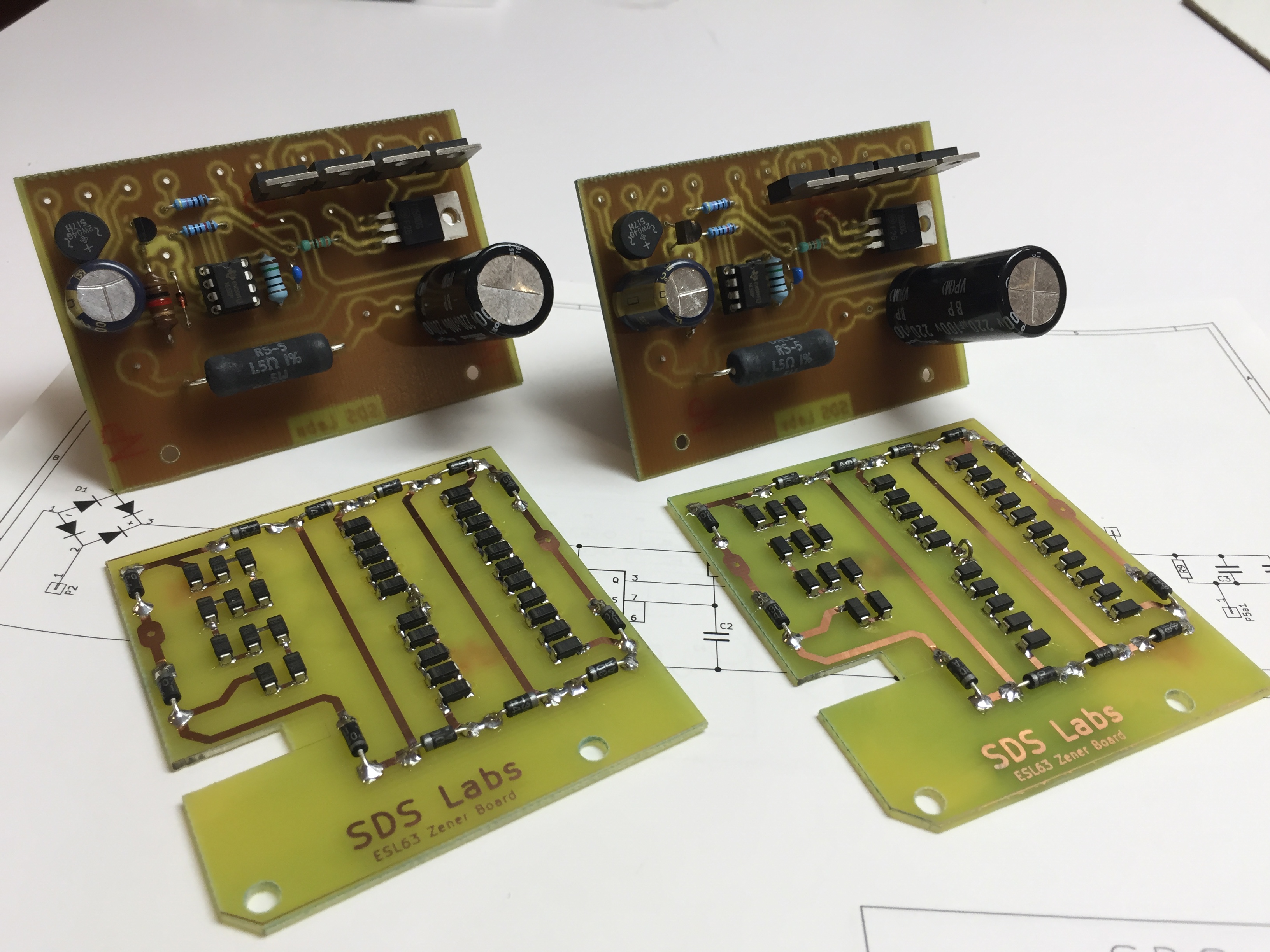
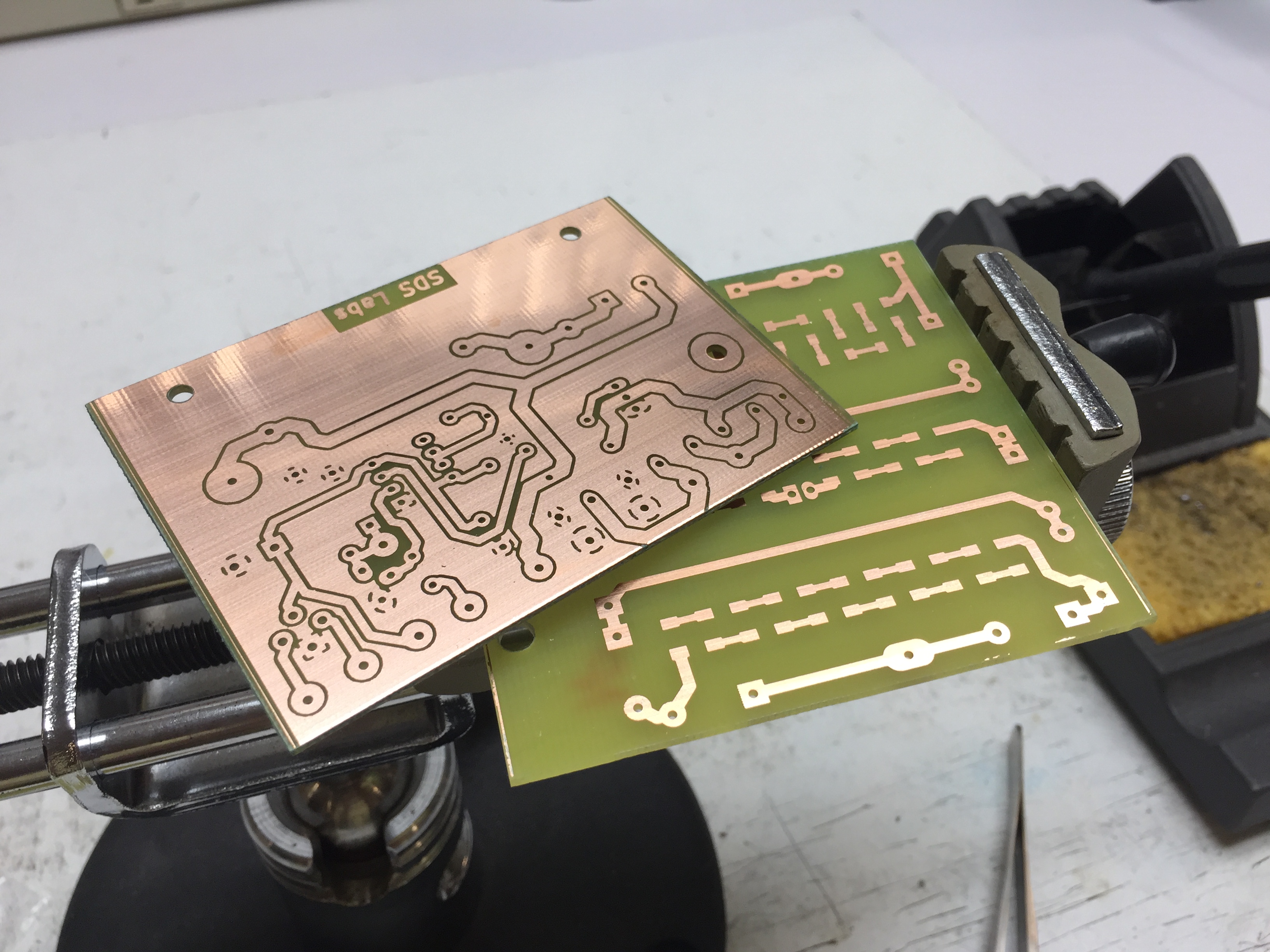
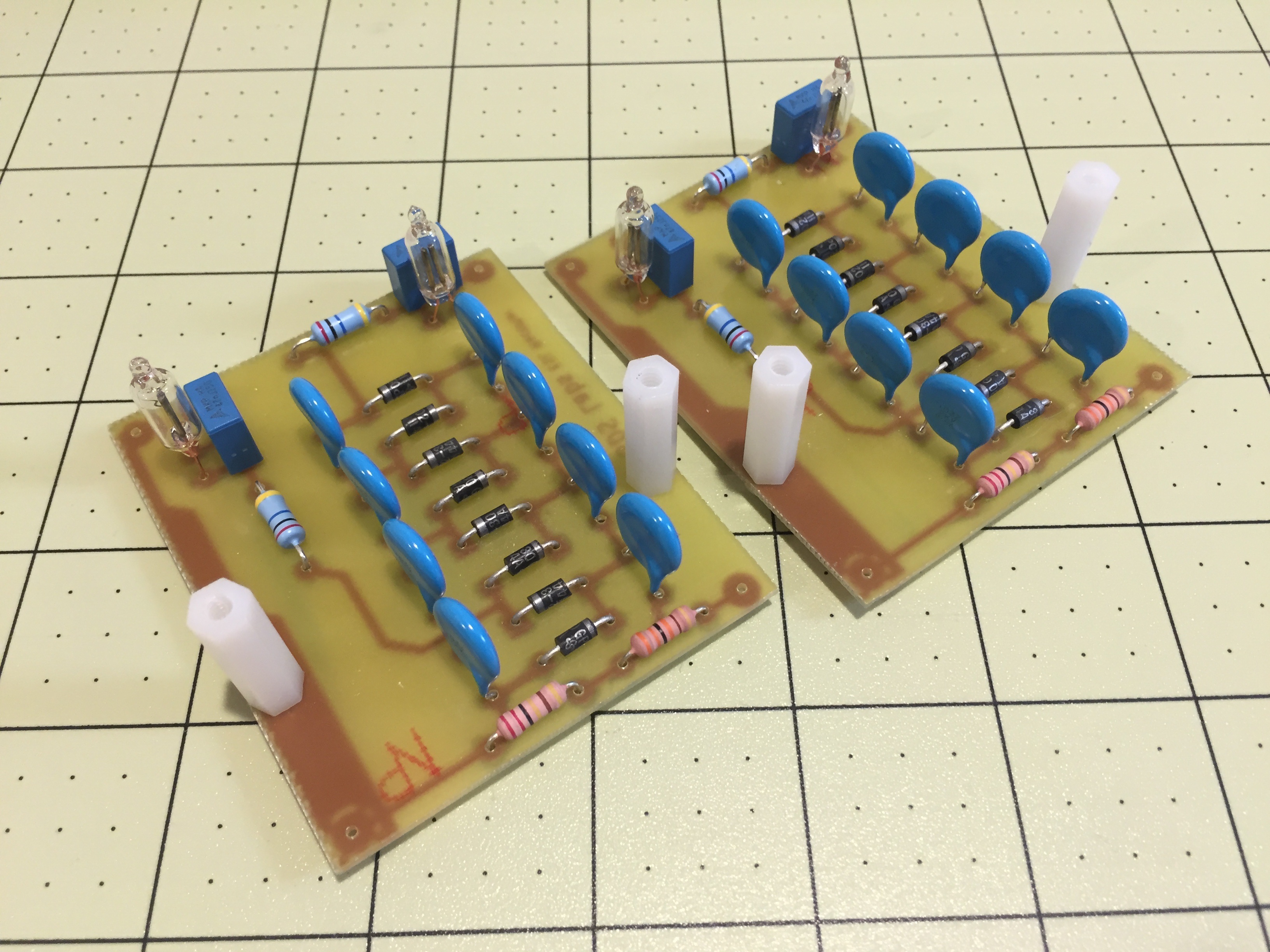
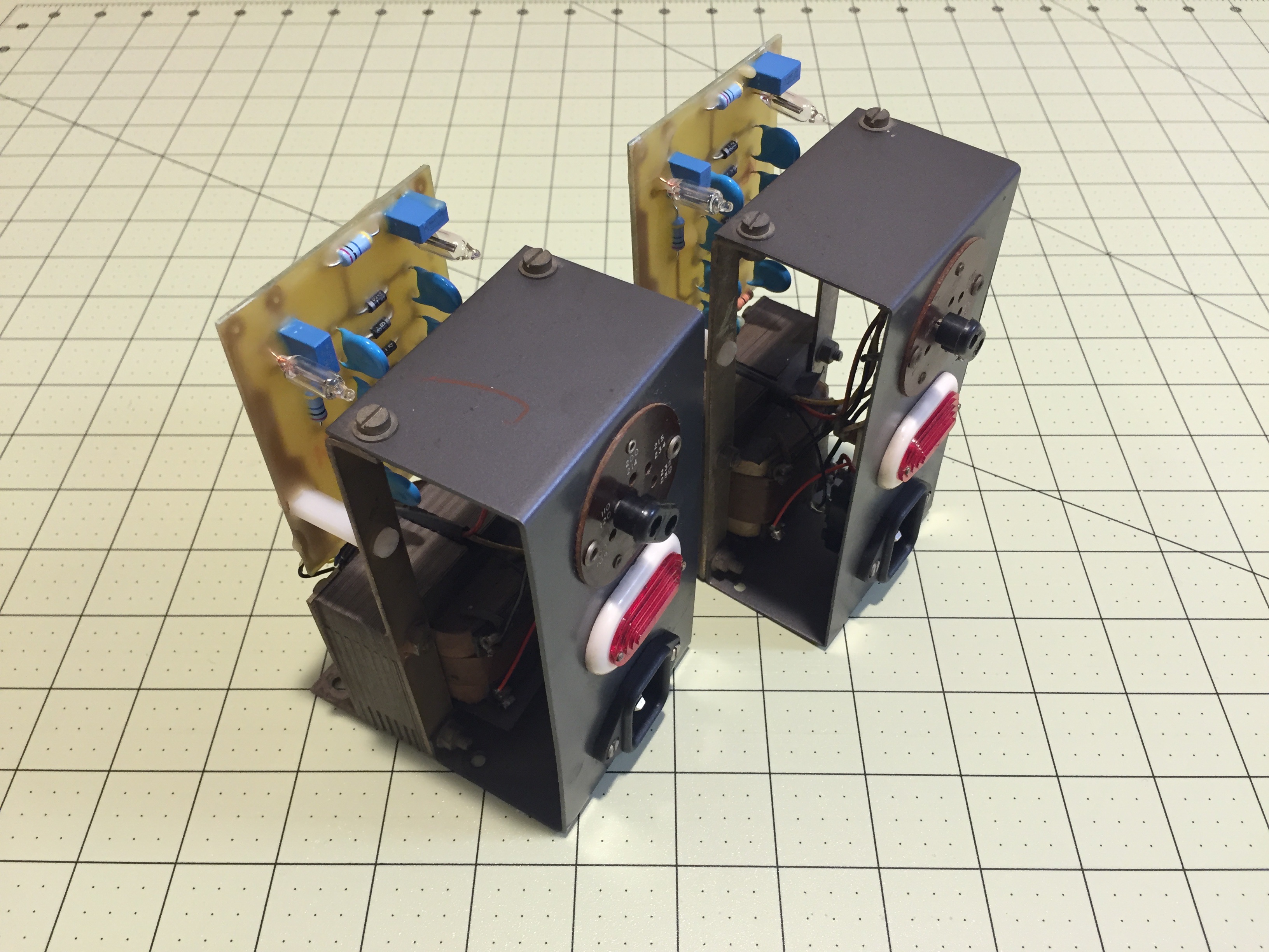
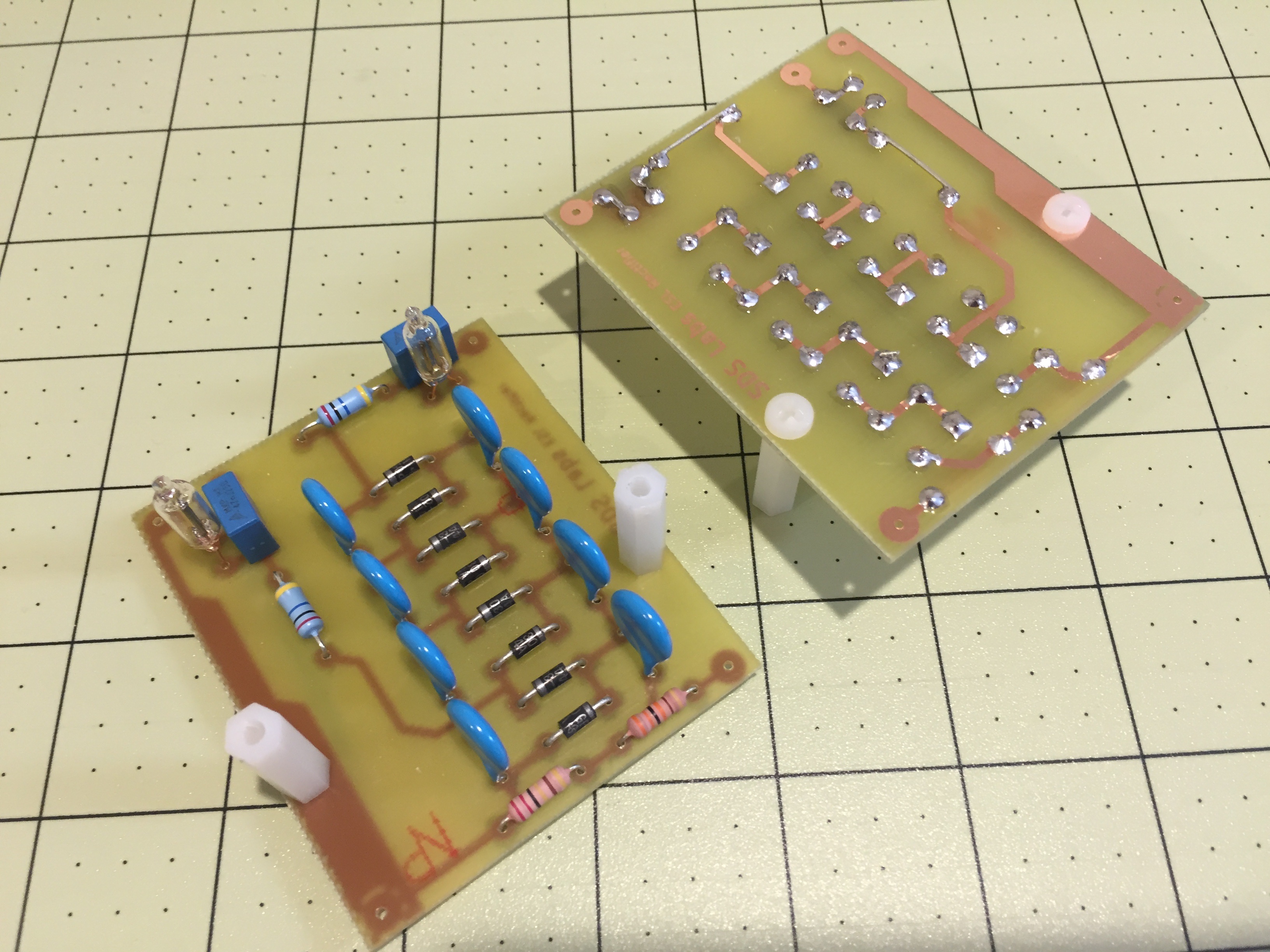
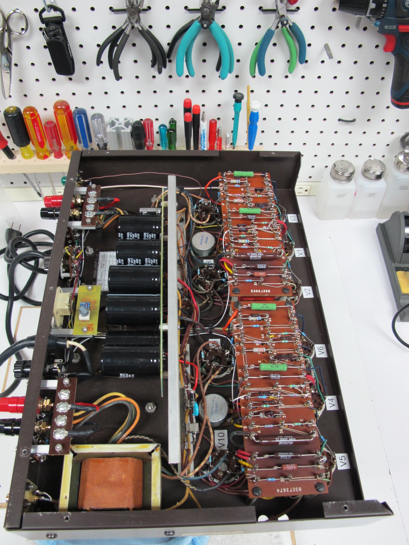
This input board is slightly different than the others I’ve seen. First the voltage gain stage is a paralleled 12AT7 dual triode. That stage feeds a long tail pair phase splitter. The phase splitter has a balance adjustment potentiometer. Each output tube has it’s own bias adjustment potentiometer as well. This input board is a nice compliment to the power supply board that is on my site as well. The input board area is fairly small to accommodate a four tube circuit and the requisite coupling caps and other parts. So to get around this limitation, the coupling capacitors are installed under the board. All the resistors and other components are installed on the top of the board with the tubes.
So how does it sound? Well, when combined with my capboard and using the Triode Electronics Dynaclone transformers, the amplifier has the typical clean and distortion midrange and treble, with bass authority that the stock Dyna ST-70 circuit cannot match. I don’t have an actual Dyna ST-70 at the moment, so I can’t do a direct comparison, but this unit is performing remarkably well both on the bench and through my ESL63’s. In the bench, this amp passes picture perfect square waves at 10Hz (2 watts), and is flat out to 80KHz (2 watts) with a small ringing at the leading and falling edges.
The Dyna ST-70 is probably the most prolific tube amp, and it’s a solid performer at what used to be a reasonable price. I got my first one out of a dumpster for free in 1992. At that time and the decade before, $50 would get you a reasonable sample. However, today there are a variety of choices that didn’t exist at the time I got my first Dyna amp; choices like Class D and Tripath amps, Chinese tube amps for a fraction of the price of domestic ones, and a large DIY community with many great solid state designs.
The Dyna ST-70 is a very balanced design, with very good output iron for the amps price-point. But the input section is a compromise and can be improved upon. I re-drew the Triode electronics design that was lost in their fire many years ago. I’ve offered up the artwork on my site for many years, and triode electronics has been selling it for many years. I have never been in love with the design due to the odd number of tubes. The ST-70 has separate filament windings for each channel. So with an odd number of tubes, one channel has more filament load than the other channel.
So fast forwarding a couple decades, there are Dyna clones from a couple of manufacturers, and more input board options than ever. So there’s really no reason for me to have designed and built another one, but I did it anyway.
This input board is slightly different than the others I’ve seen. First the voltage gain stage is a paralleled 12AT7 dual triode. That stage feeds a long tail pair phase splitter. The phase splitter has a balance adjustment potentiometer. Each output tube has it’s own bias adjustment potentiometer as well. This input board is a nice compliment to the power supply board that is on my site as well. The input board area is fairly small to accommodate a four tube circuit and the requisite coupling caps and other parts. So to get around this limitation, the coupling capacitors are installed under the board. All the resistors and other components are installed on the top of the board with the tubes.
So how does it sound? Well, when combined with my capboard and using the Triode Electronics Dynaclone transformers, the amplifier has the typical clean and distortion midrange and treble, with bass authority that the stock Dyna ST-70 circuit cannot match. I don’t have an actual Dyna ST-70 at the moment, so I can’t do a direct comparison, but this unit is performing remarkably well both on the bench and through my ESL63’s. In the bench, this amp passes picture perfect square waves at 10Hz (2 watts), and is flat out to 80KHz (2 watts) with a small ringing at the leading and falling edges.
Here is the schematic: Schematic
Here is the Layout: Layout