The Quad ESL-63 has gone through several revisions of the input protection boards. The latest design uses a bridge rectifier and zener diode stack similar to the treble panel protection circuit in the Original ESL’s. This is combined with a simplified arc detection and clamp circuit. This latest design has been used in all the subsequent Quad ESL models from the 988, 2805, and 2812 models.
The arcing clamp circuit senses the electrical field from an arc with a short antenna by rectifying the signal with a diode. This rectified signal turns on a transistor which clamps the input on a 555 timer chip wired as a one-shot. This then turns on a TRIAC which shorts the input to the speaker.
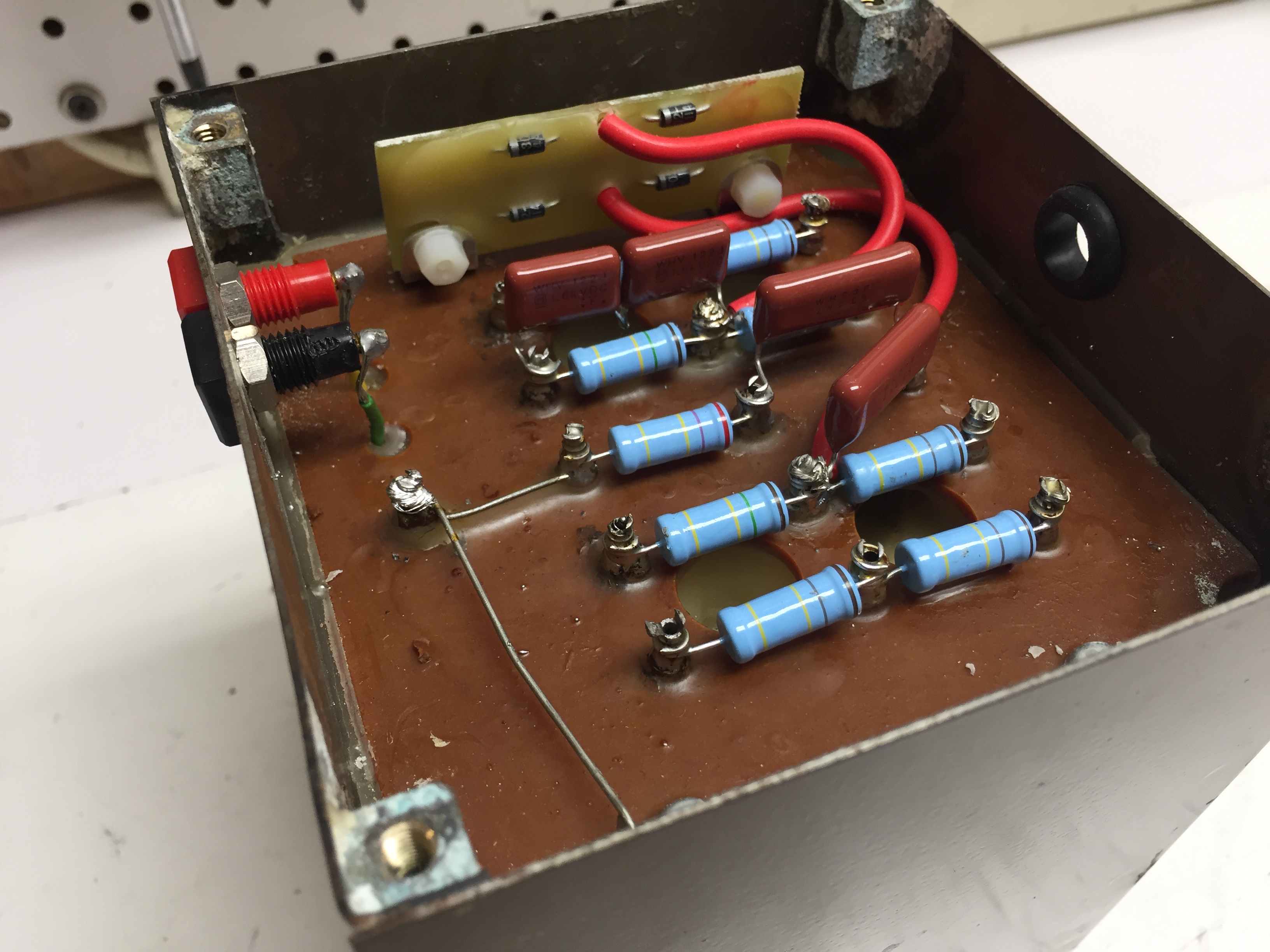
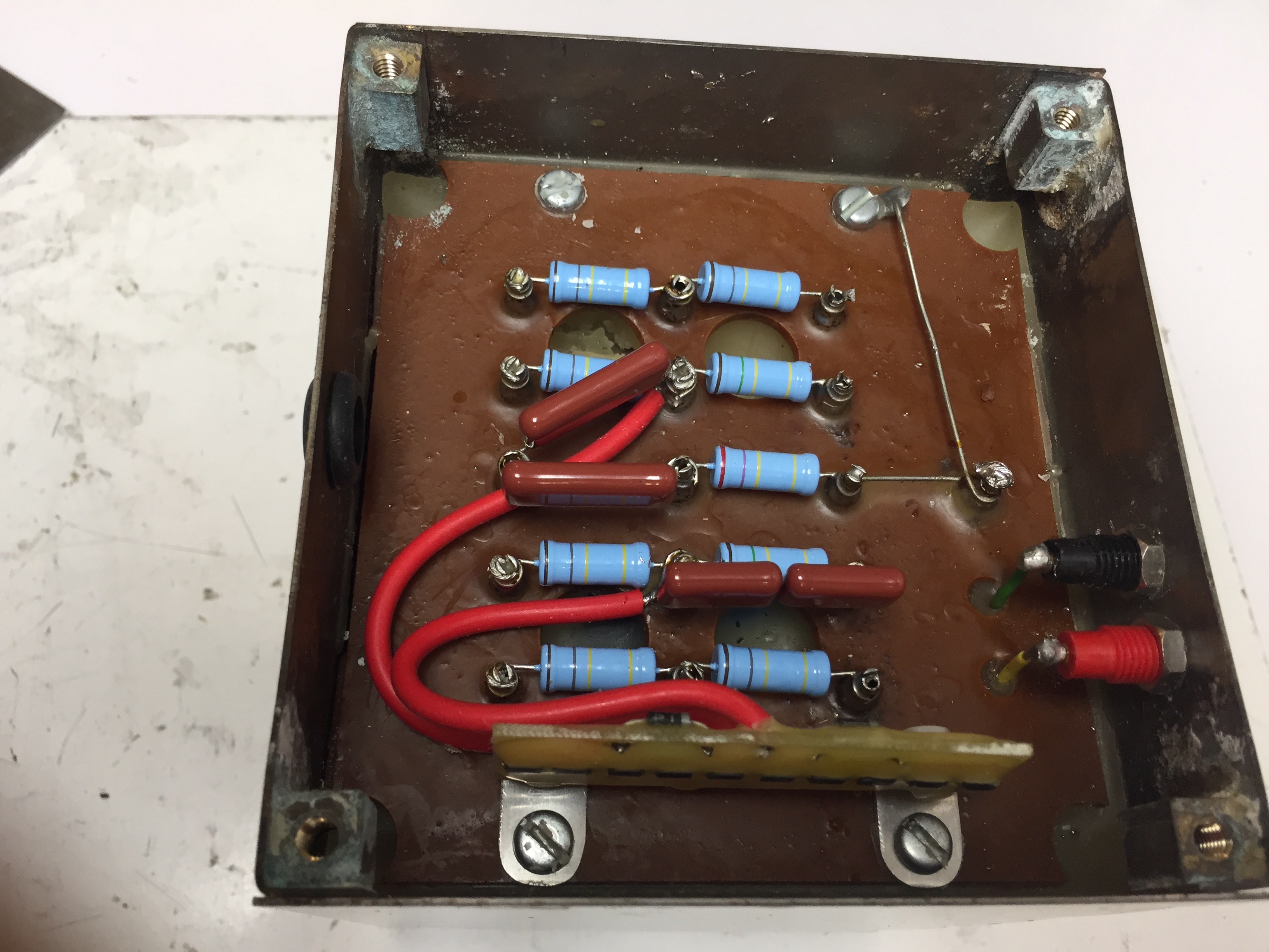
The OEM arc clamp board also contains the input ballast resistors as well as a capacitor “zobel” for the input transformers. In the OEM circuit the input series resistor (1.5ohms) and parallel capacitor (220uf) are mounted to the chassis.
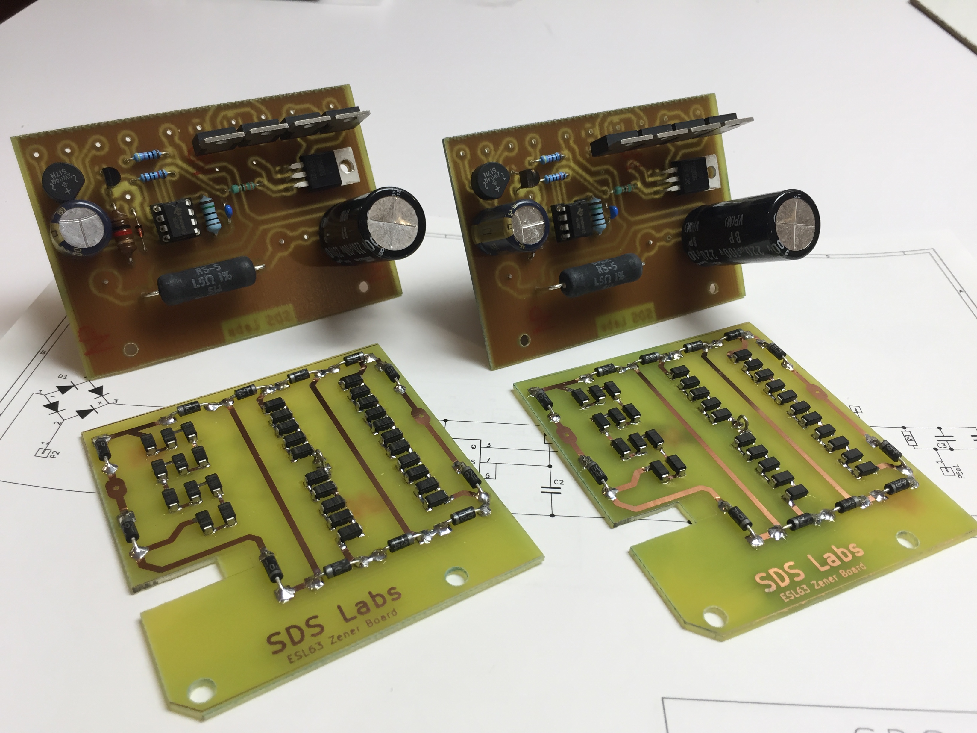
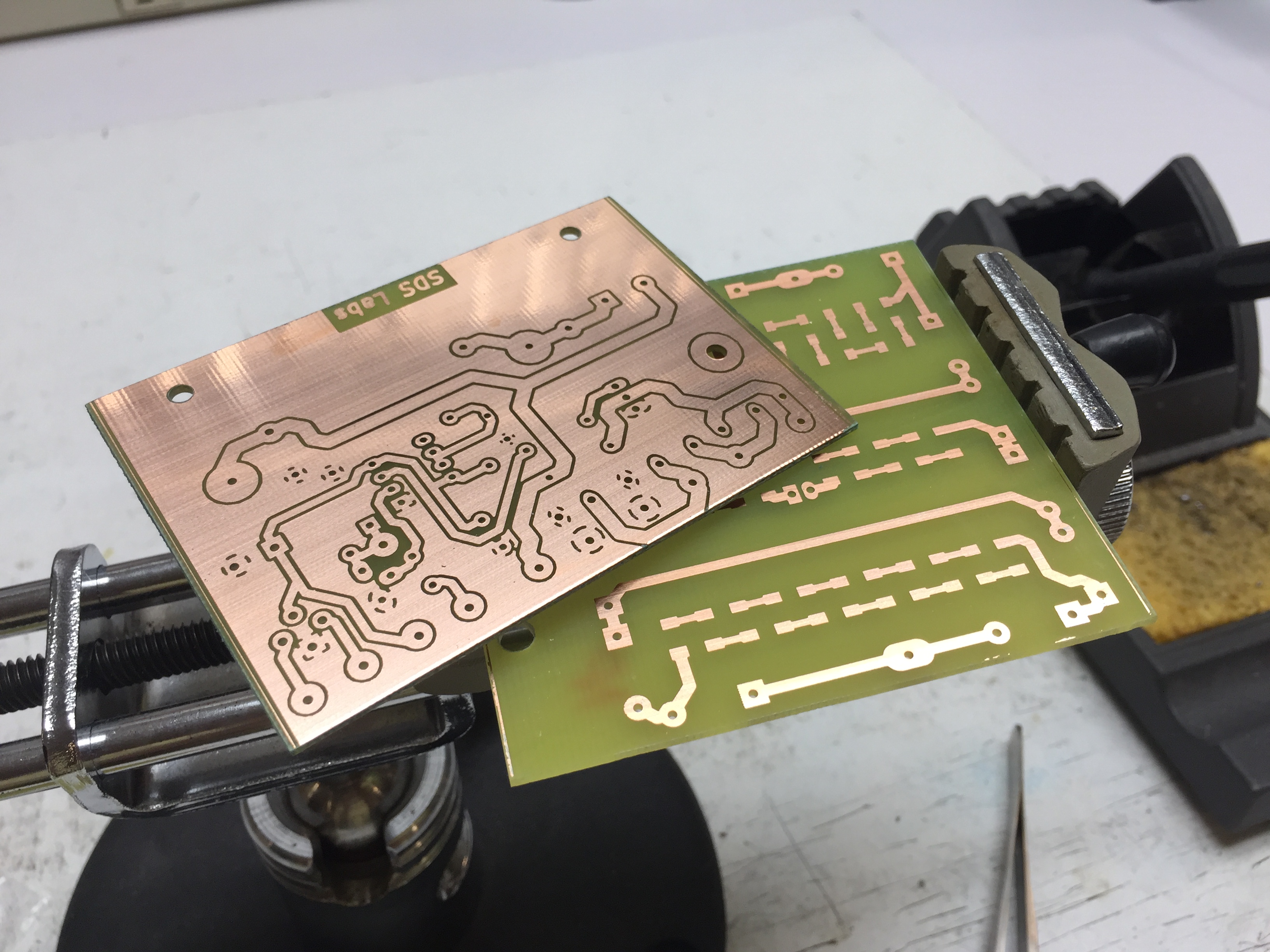
I have designed a replacement zener clamp board which is much like the OEM unit, but uses surface mount zener diodes. I have also designed a replacement arc clamp board which uses precision ballast resistors and also incorporates the input resistor and parallel electrolytic capacitor. And a needed improvement is provisions for adding a healthy sized film bypass capacitor across the input electrolytic.
The schematics and layouts of both boards are here:
ESL-63 Arc Clamp Board Schematic
ESL-63 Zener Clamp Board Schematic
ESL-63 Zener Clamp Board Layout