Blog Archives

Sunday, March 28th, 2010 | Author:

The Jordan JX-92 is a great little driver, but has some raggedness in the upper frequencies.  Below about 4KHz, the driver has a clarity and an uncolored response that is very impressive.  The bass response, while not window-rattling, is really impressive for a 5.5″ driver.  To take the good stuff from the Jordan and not get the bad, I decided to mate it up with a tweeter.  But not any old dome tweeter would do the Jordan justice.  I considered a ribbon, but I kept coming back to the Vifa XT-25 as a great mate for the Jordan.  The crossover point is nice and high, so the XT-25 won’t be stressed.  The character of the XT-25 also matches the Jordan driver quite nicely.  Finally, the deciding factor:  I had a pair of them.

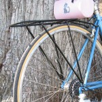
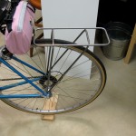
The beginning of this project can be seen here:  http://getinthewoodchipper.com/?p=181 Where there are pictures of the cabinets being routed, and the drivers mounted.

The jordan is designed to not roll off in the treble, and the Vifa XT-25 doesn’t seem to know it’s tweeter.  So in order to get a reasonable crossover rate and not have a huge upper midrange muddying region where both drivers are contributing, the drivers need to be crossed over pretty hard.  After messing with 2nd order crossovers, it was pretty obvious that it wasn’t rolling the drivers off fast enough.  4th order filters worked pretty well, but the parts count was crazy, and the sound seemed somewhat pinched off and odd sounding in the crossover region.  I settled on a 3rd order crossover (electrical) for both the woofer and tweeter.  The woofer crossover is a butterworth topology, and the tweeter circuit is somewhat of an unknown that compliments the response of the woofer.

I used my computer and an external USB soundcard with my impedance bridge and microphone pre-amplifier, a Panasonic WM-61A electret microphone capsule, and my modified Dyna SCA-35 to drive the speaker as the basis of the measurement hardware to design the crossover.  I used two different software suites to do the driver response measurement.

I used Fuzzmeasure, which uses a swept-sine deconvolution to calculate the impulse response.  I also used software of my own design which uses MLS sequences to calculate the driver impulse response.  Fuzzmeasure is a very slick and easy to use program, but it seems to show a rosy picture of the response.   The drivers are in no way as flat as it makes them out to be, but the crossover region seems to be represented accurately.  Small changes in the crossover show up in the response.  Update:  I was over-driving my Fuzzmeasure measurements and that causes the flat-top readings shown below. My program is also slick and works the way I want it to, and I have control and understanding of the processing the program does.  My code also matches the impulse response of Loudspeaker Lab.

Here is the speaker response as measured with my software.  Note that my  impulse response is “windowed ” to eliminate the room response.  But the windowing process also rolls off the bass response, so anything below about 300Hz is artificially rolled off on the plots below.  The first plot is the impulse response, woofer and tweeter response, and the null from the tweeter polarity reversal.  The second plot shows the port contribution and woofer null with close microphone placement at the driver cone and port exit.  The red woofer trace shows the current port tuning at about 55Hz.  The Jordan is still breaking in, and I’ll lengthen the port to tune it to about 45Hz when the Fs of the Jordan drops.

The output of Fuzzmeasure is shown below.  Note the insane smoothness of the Jordan driver (compare this to every other measurement you’ve ever seen of the Jordan).  But the crossover information looks very similar.  Update:  The smoothness is due to over-driving my input signal, which was not obvious to me.  I’ve since fixed my problem and the Fuzzmeasure readings and my software readings agree very well.  Fuzzmeasure is a great Macintosh program for speaker and audio measurements.

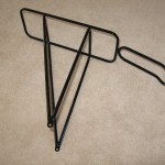
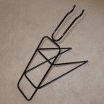
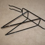
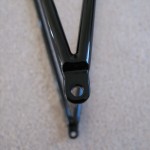
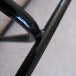
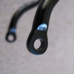
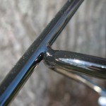
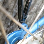
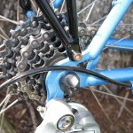
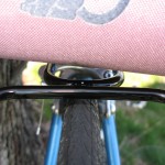
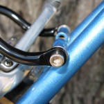
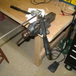
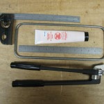
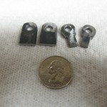
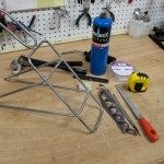
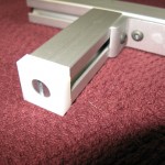
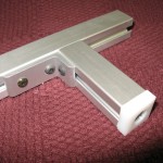
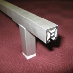
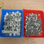
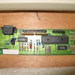
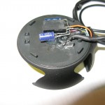
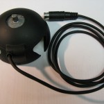
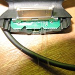
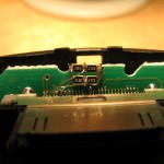
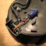
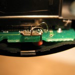
Here’s some pictures of the crossover build-up process:

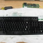
PCB Layout File:  jordan2way_crossoverPCB

Category: Audio  | Tags: , , , , ,  | Comments off
Tuesday, March 16th, 2010 | Author:

My wife has been lampworking glass beads and is starting to sell her wares.  In order to take pictures of her handiwork, I needed a good way to illuminate the small glass artwork.  There are many plans for simple lightboxes based on cardboard boxes on the web, but I just can’t bring myself to build any tool that I’m going to use for more than a few minutes out of cardboard.  So I built one out of 1/2″ PVC pipe and some stretchy white nearly swimsuit material.  The whole thing breaks down and stows into a canvas bag that I sewed for the purpose.  The box is sized to accept 22″ wide posterboard without cutting to act as a seamless background.  I light the box with a pair of 100 watt daylight compact fluorescent bulbs in desk lamps.   The total cost of the light box is about $12.

Category: Photography  | Tags: , ,  | Comments off
Tuesday, March 16th, 2010 | Author:

I’ve been building speakers for myself and others as well as repairing Quad Electrostatic speakers for nearly twenty years.  A couple of my designs are shown on my website, as well as instructions and descriptions of how to repair the Quad ESLs.  One key tool needed in speaker design and repair is the ability to measure the speakers acoustical response.  I have used  Loudspeaker Lab to measure passive components, driver TS parameters, and speaker impulse response and sweeps.  Lately I’ve been using Fuzzmeasure on my Mac, which is a nice and simple package, and works well.  But nothing works exactly like you like to work except software you write yourself.  I have a complete passive component measuring, Driver TS parameter calculating, and speaker impulse and sweep response measuring suite written in LabView.  I’ll be posting a description of my software suite and lots of screenshots soon.

Regardless of the software used, a good microphone pre-amplifier is needed.  In 2002, I designed a measurement bridge loosely based on the Loudspeaker Lab box.  The controls were designed to match the Loudspeaker Lab box, and my measurement box contains a lot of the same functionality, but in a higher performance, more battery hungry version.  The measurement box contains a low noise wide bandwidth microphone pre-amp, an amplified impedance bridge, and an extra channel of buffering for amplifier compensation when measuring speakers.  In addition, I have a built in reference resistor (0.005%) to calibrate the impedance bridge.

This bridge allows me to measure and match crossover components (caps, resistors and inductors), measure driver Thiele-Small parameters (Delta Mass), and measure speakers; both impulse response (MLS based), and in-room sweeps.  I use this measurement box in conjunction with Panasonic WM-61A electret microphones.

Here is the schematic for my measurement bridge:

And here’s a few pictures of the measurement box itself.  It loves to eat 9V batteries:

Monday, March 15th, 2010 | Author:

I’ve had a pair of Jordan JX-92S sitting around for a year or so (part of a DIYAudio group buy).  I built a set of transmission line speakers around these drivers several years ago, and while they are amazing drivers, they do have issues in the treble.   So given that I also have a pair of the very nice Vifa XT-25 tweeters that should mate nicely with the Jordan, these drivers should make a great little speaker.  The JX-92’s really work well in a transmission line or a quarter wave tube, but I was looking for a much smaller speaker.  The Jordan is an amazing driver, but it’s still a small 5 1/2″ driver.

My measurements after a day of break-in show that the JX-92 has the following parameters:

Fs Qms Qes Qts Vas
62.0304 2.4919 0.8639 0.6415 7.8288
Re Mms no (%) Sp So
5.1570 7.2457 0.2076 85.3730 87.2273

The Fs is unusually high, which indicates that the driver is not yet fully broken in.  However the Q of the driver isn’t very far removed from what others are getting from these new “more efficient” JX-92 drivers.  The Q being so high is bad for my hopes of making a small speaker from this driver.  Based on these parameters, I need a 1.3cu-ft box if I was going to used a ported enclosure.  That’s a huge floor-standing box.  A transmission line would also be a slightly smaller floor-standing box.  A sealed enclosure would be small, and completely anemic.

As much as I like the Jordan drivers, A speaker with a 0.5 cu-ft enclosure or larger lends itself to a a whole other class of drivers.  For example in a 0.5 cu-ft vented box, the Zaph SR-71 speaker outclasses the jordan in every way (in the midrange down; with a driver that is 1/3 the cost of a jordan).  A floorstanding speaker lends itself to even more impressive driver and frequency extension.  So in order for the Jordan JX-92 to be a useful driver to me, it HAS to live in a small enclosure.

I bought a set of the Parts Express 0.25 cu-ft enclosures and have cut them into a set of ported enclosures.   I’ve got the port tuned for about 55 Hz at this point, but it should actually be a bit lower.  I’m considering trying an extended bass shelf design in this little enclosure.

The problem with this driver selection is that the woofer really is trying to be a tweeter, and the tweeter thinks it’s a woofer.  So I’m slapping both drivers down with third order crossovers.  It’s a good first cut, but not perfect.  Coming up will be the final crossover design and my Labview speaker measurement software in action.  I’m using Fuzzmeasure and my own software in a MacBook Pro with an M-Audio Transit USB soundcard.

Below are some pictures of  the fabrication and some of the crossover design.

Friday, April 24th, 2009 | Author:

$40 later the rack has been nicely powder coated. Thanks ProStrip. I dropped it off on a Wednesday afternoon, and got it back Friday afternoon. It turned out pretty nicely, and fits well, both bare and with a rack trunk in place.

Category: Bicycling, Uncategorized  | Tags: , , , ,  | Comments off
Sunday, April 12th, 2009 | Author:

My wife is a bit under-tall and it is a bit of a struggle to get a proper fitting bicycle for her. Fortunately, the bikes by Georgena Terry fit her well. She has also seen the light and rides a Brooks leather saddle. Her favorite model is the sprung Champion Flyer “S”. The combination of the low seat height and the seat springs make it impossible to fit her bike with a traditional rear rack. A rack can almost be kludged under the seat if the style is chosen carefully, but the problem remains that a bag on top of the rack is in the way of the seat.

Being a firm believer in everybody carrying their own weight, I decided to fix this problem. I got some 5/16″ 0.035″ wall thickness 4130 Chrome-Moly aircraft tubing and a bit of silver solder and set out to make a rack just for her bike (or any 18.5″ 700c Terry frame).

I don’t have a proper torch, or much in the way of proper tooling, so I knew this was going to be an adventure. Silver solder has a melting point below the flame temperature of propane, so I knew at least I stood a chance at making a joint. The one tool I bought after trying lesser tubing benders is a Ridgid tubing bender. The cheap tubing benders sold at Harbor Freight and the like work well for copper and aluminum tubing but really fall flat on thin walled steel. The Ridgid made bends that are a thing of beauty.

Shown below is the results of my efforts using a few hand tools, the tubing bender, and a propane torch. The rack is set back far enough that with a rack trunk in place there is still some room between my wife’s posterior and the front of the trunk. In the pictures, the fillets are nearly complete with final sanding and finish work left to do. The final step is to powder coat the rack.

Friday, April 03rd, 2009 | Author:

A dishing tool is used to check that the rim is centered between the hub ends during wheel building or truing. In the mid-1980’s, being a poor high-school kid, I built a wheel dishing tool out of a 2×4 with a bite cut out of the center, and a screw assembly from a cheap stamped c-clamp. Over the years the tool took a beating from multiple moves and not enough care in storing it.

I have the cheapest truing stand known to man, which does not automatically center the feelers so if I’m not careful, I can walk the rim out of dish while truing.

I was going to buy a dishing tool, but the ones available today aren’t too impressive and cost more than one I could build out of 80-20 aluminum extrusions. I used my little machine tools and put one together for about $30. The main components are 10 series single slot 80-20; the main beam is 30″ long, and the arms are 3 inches long. The center feeler is a piece of 1/4-20 all thread with some hardware store knobs on the outside, and a simple turned feeler on the inside. The pictures are below:

Category: Bicycling  | Tags: , , ,  | One Comment
Wednesday, December 31st, 2008 | Author:

Well after owning my Model M keyboard for nearly a decade, I decided that my key-cap cleaning and case wiping wasn’t enough. So I carefully removed the keyboard itself from the keyboard case and cleaned everything I could reach. This isn’t typically blog-worthy, but this is the legendary IBM Model M keyboard; the one true keyboard. So much has been written about this wonderful piece of engineering that I won’t elaborate. Wikipedia does a good job of it: Model M

I love my keyboard, and use it frequently. I do a lot of work on laptops these days and the Apple low profile aluminum keyboard is slowly winning me over with is sweet short throw sweetness. But the tactile feel and sound of typing on a Model M is a thing of beauty.

Sheldon

Monday, December 08th, 2008 | Author:

The original plan was to add a 5 volt regulator in the Dension cradle cable. I was planning to add it about 6 inches from the connector and heat shrink it when I was done like some sort of cable goiter. As I was checking out the back cavity of the cradle I realized that the regulator would damn near fit inside it. However, with the metal attachment bracket it wouldn’t quite fit. I ground down the metal bracket and sanded down the regulator a bit and everything fit perfectly. I added filter caps before and after the regulator to suppress noise and called it as day. The cradle is working well and is ready to install. As usual, pictures are below.

Monday, December 08th, 2008 | Author:

Last night I installed the voltage divider assembly into the Dension cradle.  I thought I had some fine soldering tools but my smallest Metcal iron tip looks like a Louisville Slugger next to the 30 pin cock connector pins.  It took some steady hands (which apparently I don’t have either), and some good diffuse light to make these connections.  I used a strand of silver plated copper wire to make the connections, and a piece of the full stranded wire to make the power connection to the voltage divider assembly.

It would have been a little less kludgy to make a new circuit board with the proper resistor divider traces on the board, but I’m not sure that I can make a boar with traces fine enough to reliably fit the connector.  I am also concerned that I couldn’t get the connector off the existing board without damaging it.  So this is the result.  It seems to work quite well at this point.

The next step is to step down the power coming into the cradle from 12(ish) volts to 5 volts.  A linear regulator doing this job would be dumping more power into heat than it provides to the iPhone for charging, which not only may overload the factory head unit, also requires the linear regulator be heat sunk somewhere.  V-Infinity has a really snazzy switching regulator that has an efficiency of about 92%. This means that during full charging, the regulator will only dissipate about 0.2 watts and will not need a heat sink.

Sheldon